No products in the cart.
How to install upgrade select battery and upgrade your stock chassis ground for better power flow.
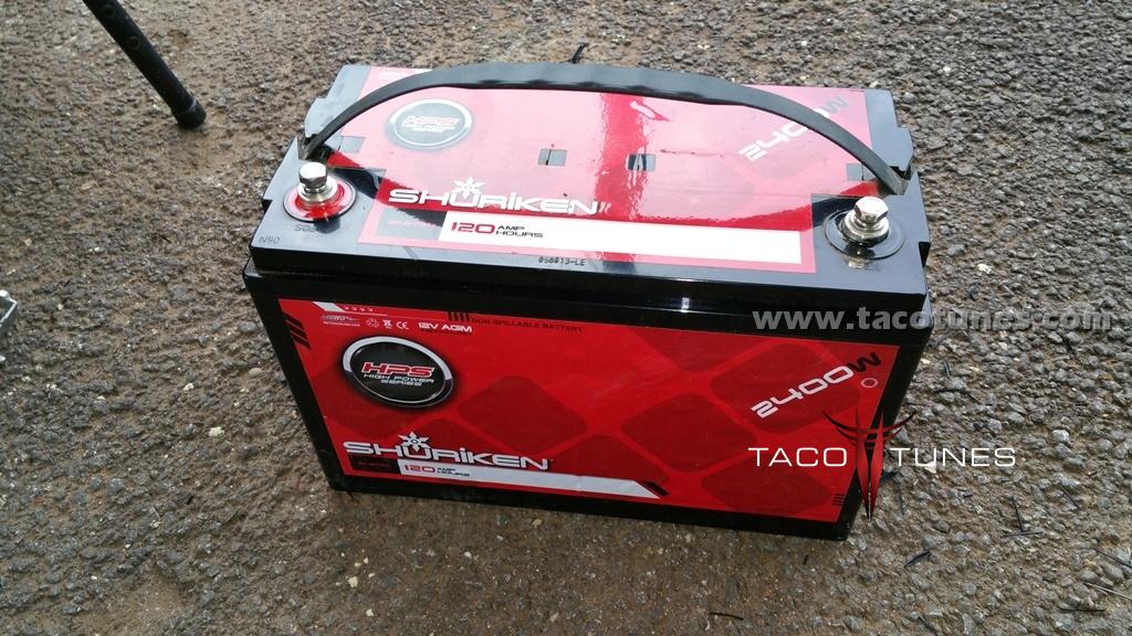
How to install upgrade select battery and upgrade your stock chassis ground for better power flow in your Toyota Tundra.
How to install upgrade select battery and upgrade your stock chassis ground for better power flow in your Toyota Tundra. Don’t waste your money on a capacitor.
Below we have performed a battery upgrade to assist with the additional power requirements from a higher end stereo system. If you would like to see more info on selecting batteries and understand why we chose this battery please visit the post – How to select a battery for your Toyota Tundra . For the record, the best route for doing this type of upgrade is using copper crimps and solder. However, many will not have the tools or have the knowledge to e able to crimp and solder heavy gauge wiring. We have field tested this setup on a number of Toyota Tundras with great results.
If you are interested, we offer this kit along with a battery in a bundled kit. The terminals will be pre-crimped and heat shrunk, you will need cable cutters, Allen wrenches & socket set to complete installation.
In the write up we will take you through upgrading the stock wet cell battery to a high quality AGM battery.
The parts we used in this upgrade are as follows:
Positive Side:
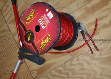
2 – 4 gauge 16″ Stinger Cable – Red
2 – 4 gauge copper battery ring terminals
2 – battery cable splicers (non soldering)
2 – 4 gauge 2″ marine grade heat shrink with sealing glue
1 – 7 feet 1/2″ split loom
1 – 3 feet 3/4″ split loom
20 – zip ties
Negative Side:
1 – battery cable ring terminal (non soldering)
1 – 1/0 Gauge 24″ Stinger Power Cable – Black
2 – 1/0 Gauge copper battery terminals
1 – 2 feet 3/4″ split loom
1 – 1 foot 1/2″ split loom
Tools Used:
Large crimping tool
Large cable cutters
Heat Gun
Allen Wrenches
Metric Socket Set
Battery:
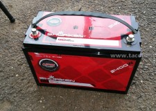
Shuriken 120BT
TEXT:
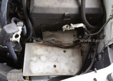
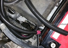
Picture of Toyota Tundra with stock battery removed.
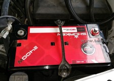
We will be installing the Shuriken BT120 AGM battery. Be sure to check out our “how to select a battery for your Tundra”!
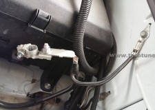
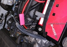
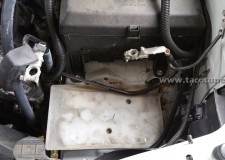
The stock battery has been removed. Here you can see the positive and negative terminals disconnected from the battery.
To avoid any confusion, we will focus on the negative terminals first. It is crucial you do not mix up your cables. Serious damage or injury can occur.
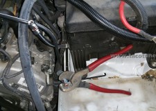
Cut off the negative battery wire as close as you can to the terminal. Try to avoid cutting the terminal, it might damage your cable / wire cutters.
We will be upgrading the chassis ground with a 1/0 cable – roughly 4 times thicker / heavier than the stock 8 gauge (roughly) stock cable.
The negative chassis ground cable has been removed. We are test fitting the battery to ensure proper length of the negative cable we will be adjusting to work with the new battery. NOTE: The battery terminals will be opposite of the stock location.
Remove the black tape and extra cover shown on the negative cable. We will be covering this wire with split loom.
Be sure to leave a little extra cable to work with.
Using your cable cutters or a razor carefully remove around 1” inch of the insulation. For best results be sure to measure it against the new negative terminal.
Insert the exposed cable into the negative terminal as shown. Then using an allen wrench be sure to tighten the locking screw.
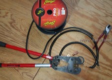
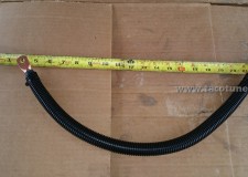
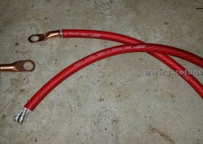
Next we will manufacture the replacement / upgraded chassis ground. In the picture you can see the 1/0 cable next to 4 gauge cable. We are using copper battery terminals sized for your Toyota Tundra. Using the monster crimpers, we will permanently attach the battery terminals to the cable.
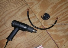
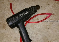
Using a heat gun we will apply marine grade heat shrink that contains a sealing agent.
After sealing the connections, we will cover the cable in split loom and zip tie the ends.
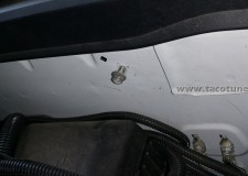
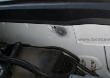
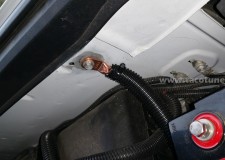
In this step we will remove enough paint and primer to ensure proper conductivity between the new chassis cable and battery.
Using sandpaper remove paint to expose metal to ensure a good ground.
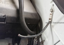
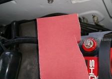
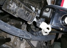
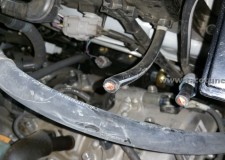
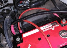
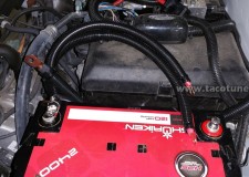
Install the new chassis ground as shown. DO NOT ATTACH TO BATTERY UNTIL ALL STEPS COMPLETED. Connect the GROUND wires to the battery last! You may want to label the wires to ensure you do not mix them up.
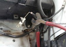
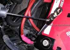
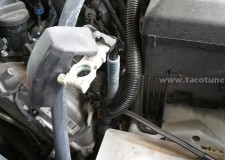
Remove the positive battery terminal from the positive battery wires by removing the bolt.
Picture of the stock wires with the battery terminal removed.
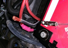
Cut the wires as closely to the connectors. You will also need to remove some of the loom to gain access to the wire as shown.
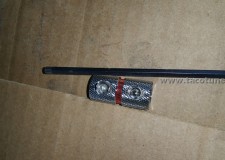
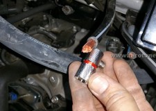
Here you can see the solderless splice. Strip away enough of the insulation to go half way into the splice.
If you are purchasing one of our kits you do not need to test fit the battery. With the battery removed you will strip away the insulation as shown.
In this step we are going to manufacture the positive cable wire extensions. Here you can see the battery terminals, heat shrink and 4 gauge wiring.
Picture of 4 gauge wiring & terminals
Picture of 4 crimped terminals and marine grade heat shrinking with sealing agent.
Attach the positive wire extension to the splicing kit. Be sure to tighten, wiggle cables and then tighten again.
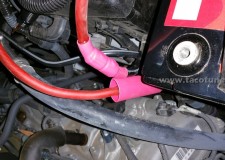
After you have tightened both splice kits, you will use your heat gun to heat the marine grade heat shrink. Be sure the heatshrink is HEAVY duty. If you are using a lower quality heatshrink, you will want to cover the heat shrink with electrical tape to ensure the cables are properly protected from accidental grounding.
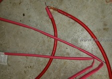
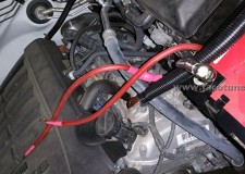
Picture of the positive cables ready for split loom.
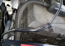
Install the ½” split loom on the upper part of the cable as shown. Then install the ¾” split loom on the lower half of the cable. Using the zip ties ensure the split loom will stay in place.
The lower part of cable & splicer will require
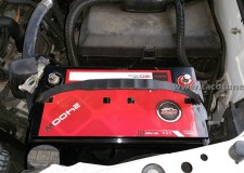
The stock battery tie down kit will work, but you will need to “wrestle” with it a little to get it installed.
Remove the stock tray before installing the battery.
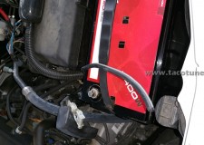
Not shown in this picture, wrap black electrical tape around the splicer. This will ensure you have multiple layers of protection.
