Thank you for purchasing the tacotunes.com system 1 complete audio upgrade. This system will allow you to keep your stock head unit and utilize your existing speaker wiring system in your Toyota 4Runner. This setup will save you a lot of time over our higher end SQ1 systems. In addition, you will be able to return you truck back to stock in the event you sale or trade the vehicle. Be sure to save ALL your stock parts.
Following the instructions below is crucial to a successful installation. We recommend prepping the following items the day before you begin your installation. This will ensure all the parts are at your disposal. We highly recommend that you take your time and NOT be in a time crunch when doing this install. There are a couple of steps where it will help to have a buddy help you out. Not necessary but makes it easier. Do NOT start drinking your favorite beverage until recommend below. Plus be sure to keep your mind sharp. By getting the installation done right the first time you will enjoy years of quality sound in your Toyota 4Runner. Shortcuts and rushing through the install will cause issues down the road. Take your time enjoy the install.
Mount your crossovers to the provided crossover mounts. (see speaker install video)
Connect the 18g & 16g wiring to the crossovers
If mounting your tweeters in sail panels, prepare your sail panels the night before and use some black caulk if necessary to secure the tweeters to your sail panels.
Assemble your amp rack, amplifier, distribution block etc. (see video below)
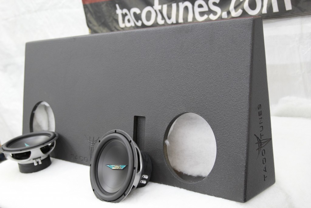
Assemble your subwoofer / subwoofer box. (see video below)
Watch installation videos to understand the process.
Get your six pack on ice. DO NOT OPEN until instructed! 🙂
Go over checklist and ensure all parts are in the package. We have a checklist that we do on EACH system. But we are human so it is possible a part was missed.
Installation: 4 – 8 hours
Tear down process and steps – follow the order below.
KILL YOUR BATTERY. Remove the NEGATIVE connection from the battery and secure it AWAY from battery.
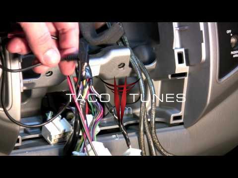
Begin the tear down process. (see tear down video)
Remove the door panels.
Remove door sills.
Remove driver side kick panel.
Remove front passenger seat.
Remove rear portion of center console.
Remove rear seats (if installing subwoofer) – have a friend help the rear seats are heavy.
Remove passenger side rear pillar panel (if installing subwoofer)
Remove stock amplifier under front passenger seat. (save the bolts)
Remove front / rear speakers.
If you will be matting your doors we suggest doing this before you being the steps below. Keep in mind matting will add a full day to your install.
Installation Steps:
Run power wire from battery to new amp location. (see video)
Assemble the fuse block and complete under hood details. (Do not connect to battery)
Run subwoofer wire to rear of vehicle per the installation video.
Install amps / amp rack per video. (do not connect output connections)
Connect input side of amp first.
Connect battery ensure the amps power up when you turn on the car.
Disconnect battery.
Connect output connections from the amplifiers.
Clear brain and take a 15 minute break.
Connect battery
Tune amplifiers per tuning video(s).
Install front / rear speakers.
Install subwoofer.
Test system – ensure playing correctly.
disconnect battery.
Install center console.
Install rear pillar panel.
Install seats BEFORE installing door panels and door sills. (battery should be unplugged)
Install kick panels and door sills.
Install door panels.
Connect battery.
Test the sound and ensure all playing properly.
Open a single beverage (not hard liquor) beat your chest and listen to your tunes for about 10 minutes.
Finish cleaning up odds and ends.
Be sure to save ALL stock parts.
Congratulations you just installed an audio system that would have cost you over $3,000 at your local audio shop.
You want to install an Alpine, Clarion, JVC, Jensen, Kenwood, Pioneer, Sony, or other brand(s) . . .but you don’t want to lose your steering wheel audio controls? We have found that in 9 out of 10 of installs, this unit will automatically detect the vehicle AND the new head unit – it then proceeds to self program.
No more soldering, programming or frustration!
NOTE: If you are using a Kenwood head unit, please be sure to contact us ahead a time. We have had a MINOR issue with some of the Kenwood head units.
How to install Steering Wheel Controls to work with new stereo in your Toyota 4Runner. We took it a step further and configured this unit especially for your Toyota.
1 – Toyota Specific Wire Harness (Select your Model below)
1 – RCA to 3.5MM adapter
2 – Crimp caps
3 – Zip ties
In most installs you don’t have to read the manual! Very easy to install with no programming:
The Installation
Once you have collected the information or printed out the information sheet on your particular vehicle from the Axxess website (www.axxessinterface.com) you’re ready to install the ASWC.
So here we go:
1) Connect the Black wire of the ASWC (pin 6) to ground. You may use the same grounding point as the aftermarket radio.
2) Connect the Red wire of the ASWC (pin 12) to a 12 volt accessory wire, one that turns on and off with the ignition key.
3) Locate the correct SWC wire(s) in the vehicles radio or secondary harness as described in the vehicle information sheet found in the Axxess website. Connect the correct wire color(s) from the
ASWC to the vehicles steering wheel control wire(s) in the vehicle.
We recommend that the wires are soldered for the best and most secure connection. T-Taps are not recommended due to the higher chance of an intermittent connection (this means you Zack).
4) If you are using an Eclipse or Kenwood radio, plug the female 3.5mm connector with the Brown and Brown/White wires into the male 3.5mm connector of the ASWC harness.
* For Kenwood radios: Connect the Kenwood SWC wire (normally Blue/Yellow) to the Brown wire of the ASWC. Isolate and tape the Brown/White wire, it will not be used.
* For Eclipse radios: Connect the Eclipse SWC wires (Normally Brown and Brown/Black) to the Brown and Brown/White wires of the ASWC. Brown goes to Brown and Brown/White goes to Brown/Black.
5) For all other radios, plug in the male 3.5mm connector of the ASWC into the back of the aftermarket radio, designated for an external SWC control interface. Please refer to the aftermarket
radios manual if you are in doubt where the 3.5mm connector of the ASWC goes.
Once all connections have been made, plug in the aftermarket radio if not done already.
Programming the ASWC
The ASWC can be programmed in two ways; it can do it by itself in Auto Detect Mode or it can be manually programmed. We will start with the Auto Detect Mode first:
Auto Detect Mode: The ASWC has the ability to auto detect certain vehicles and to know what aftermarket radio it is connected to. The vehicle info sheet from the Axxess website (www.axxessinterface.com) will show if
your vehicle would be auto detected and what action, if any, is required by you for this process to take place.
User Manual:
AXXESS STEERING WHEEL CONTROL INTERFACE
INSTALLATION
MANUAL
axxessinterface.com 800.221.0932
The ASWC is a universal steering wheel control interface that can be used on most any vehicle with
steering wheel controls. Designed to be used with today’s top aftermarket radio manufactures like
Pioneer, Sony, Alpine, Kenwood, Eclipse, JVC, and others, the ASWC is all you’ll need to retain the
OEM steering wheel controls. The ASWC has the ability to auto-detect many vehicle makes and
aftermarket radios and it will preset the steering wheel controls to the aftermarket radio automatically
so no programming is required. If desired the ASWC can be manually programmed so the user can
make the steering wheel controls function the way they want them to, only limited by the functions of
the aftermarket radio. The ASWC also has a non-volatile memory which means the ASWC will remember
the programming even if the ASWC is disconnected from the vehicle.
The ASWC is also updatable using the Axxess website (www.axxessinterface.com) and the USB-CAB
update cable. If there is an update made to the ASWC there is no need to send inventory back, or ask
for the latest version, you can update it yourself and save time and money.
What’s included in the package:
• ASWC Interface
• 12 pin harness with male 3.5mm connector
• Female 3.5mm connector with Brown and Brown/White wires
• Comprehensive Instructions
What you need to know before you begin:
1) Make sure you know the correct year, make, and model of your vehicle
2) Make sure the radio you are installing is compatible with a steering wheel control interface (Check
in owners manual)
3) Go to the Axxess website (www.axxessinterface.com) for a detailed information sheet on what
color(s) the steering wheel control wires will be in your vehicle, the location, what wire(s) to use
on the ASWC, and what, if any, programming is required. Print or write the information down so
you have it in the vehicle during the install.
Note: Though we have done extensive research and testing verifying the steering wheel control wire
colors of the vehicle we list are correct, it is still your responsibility to verify the steering wheel control
wires with a multimeter. If you find a discrepancy please notify our Tech Department at
1-800-253-TECH.
axxessinterface.com 800.221.0932
USB PORT COVER RESET BUTTON PROGRAMMING LED
PIN
1
PIN
2
PIN
3
PIN
4
PIN
5
PIN
6
PIN
12
PIN
11
PIN
10
PIN
9
PIN
8
PIN
7
A brief overview of the ASWC interface and wire harness:
On the top of the ASWC interface there are three points of interest:
1) The Programming led – this will flash rapidly when in auto detect mode, flashes slowly in manual
programming mode
2) The Reset button – Hold down button more then 2 seconds but less then 10 seconds to start auto
detect mode; hold down longer then 10 seconds to start manual programming mode
3) The slide cover for the USB update port – open this up to reveal the USB update port. Using the
USB-CAB update cable and the Axxess website you can make sure you always have the latest,
updated inventory.
Below are the wire colors of the ASWC. Please go to the Axxess website (www.axxessinterface.com)
for detailed information on your specific vehicle and what color wire(s) to use on the ASWC.
Pin 1 – Pink
Pin 2 – White/Green
Pin 3 – Orange/Green
Pin 4 – Green/Orange
Pin 5 – Gray/Red
Pin 6 – Black
Pin 7 – Blue/Pink
Pin 8 – Black/Green
Pin 9 – White (Ring of 3.5mm connector)
Pin 10 – Red (Tip of 3.5mm connector)
Pin 11 – Gray/Blue
Pin 12 – Red
Wire Insertion View
axxessinterface.com 800.221.0932
The Installation
Once you have collected the information or printed out the information sheet on your particular vehicle
from the Axxess website (www.axxessinterface.com) you’re ready to install the ASWC.
So here we go:
1) Connect the Black wire of the ASWC (pin 6) to ground. You may use the same grounding point as
the aftermarket radio.
2) Connect the Red wire of the ASWC (pin 12) to a 12 volt accessory wire, one that turns on and off
with the ignition key.
3) Locate the correct SWC wire(s) in the vehicles radio or secondary harness as described in the
vehicle information sheet found in the Axxess website. Connect the correct wire color(s) from the
ASWC to the vehicles steering wheel control wire(s) in the vehicle.
We recommend that the wires are soldered for the best and most secure connection. T-Taps are not
recommended due to the higher chance of an intermitted connection (this means you Zack).
4) If you are using an Eclipse or Kenwood radio, plug the female 3.5mm connector with the Brown
and Brown/White wires into the male 3.5mm connector of the ASWC harness.
* For Kenwood radios: Connect the Kenwood SWC wire (normally Blue/Yellow) to the Brown
wire of the ASWC. Isolate and tape the Brown/White wire, it will not be used.
* For Eclipse radios: Connect the Eclipse SWC wires (Normally Brown and Brown/Black) to the
Brown and Brown/White wires of the ASWC. Brown goes to Brown and Brown/White goes to Brown/
Black.
5) For all other radios, plug in the male 3.5mm connector of the ASWC into the back of the
aftermarket radio, designated for an external SWC control interface. Please refer to the aftermarket
radios manual if you are in doubt where the 3.5mm connector of the ASWC goes.
Once all connections have been made, plug in the aftermarket radio if not done already.
Programming the ASWC
The ASWC can be programmed in two ways; it can do it by itself in Auto Detect Mode or it can be
manually programmed. We will start with the Auto Detect Mode first:
Auto Detect Mode:
The ASWC has the ability to auto detect certain vehicles and to know what aftermarket radio it is
connected to. The vehicle info sheet from the Axxess website (www.axxessinterface.com) will show if
your vehicle would be auto detected and what action, if any, is required by you for this process to take
place.
axxessinterface.com 800.221.0932
For the Auto Detect feature to work there are 3 possible actions, however only one action will be required
by you depending on your vehicle:
1) Turn the ignition on and no other action is required.
2) Turn the ignition on, press and hold down the Volume Up button on the steering wheel.
Or
3) Turn the ignition on, press and release the Volume Up button repeatedly on the steering
wheel.
Like we said before, only one of these actions will need to be done depending on your vehicle for the
auto detect feature to work. Please refer to the vehicle info sheet in the Axxess website.
These are the steps for the Auto Detect Mode:
1) Complete connections to the vehicle and the aftermarket radio.
* If this is the first time the ASWC is being installed in a vehicle:
2) Turn the ignition on; the led will start flashing rapidly which means the ASWC is looking for the
vehicle and the radio.
3) Perform action required for your particular vehicle as noted in the vehicle info sheet.
4) After a couple of seconds the led should stop flashing and not light up for 2 seconds. At this point
do not push any buttons.
5) After the 2 seconds there will be a series of 7 flashes, some short and some long. Make a note of
which flashes were long for this may be needed later.
6) The led will pause for another 2 seconds then flash up to 9 times. Again make a note of how many
flashes.
7) This is the end of the auto detection stage. If the ASWC detected the vehicle and the radio
successfully the led will light up solid red.
8) Make sure the steering wheel control buttons function correctly in the vehicle and enjoy your radio.
So what if the led does not light up solid red? Check out troubleshooting section below.
axxessinterface.com 800.221.0932
* If the ASWC was installed in a vehicle before:
2) Turn the ignition on, the led will flash slowly
3) Hold down the reset button for more then 2 seconds but less then 10 seconds, the led will start
flashing rapidly
4) Perform action required for your particular vehicle as noted in the vehicle info sheet
5) After a couple of seconds the led should stop flashing and not light up for 2 seconds. At this point
do not push any buttons.
6) After the 2 seconds there will be a series of 7 flashes, some short and some long.
7) The led will pause another 2 seconds then a series of 9 flashes.
8) This is the end of the auto detection stage. If the ASWC detected the vehicle and the radio
successfully the led will light up solid red.
9) Make sure the steering wheel control buttons function correctly in the vehicle and enjoy your radio.
So what if the led does not light up solid red or the steering wheel controls is not working correctly
with the aftermarket radio?
Check out troubleshooting section right below.
Troubleshooting the Auto Detect Mode
So you tried the auto detect feature and at the end the led did not stay on solid red, it started flashing.
That means the ASWC did not detect the vehicle. Follow these couple steps to determine what happened:
First some basic steps:
1) Verify that you have 12 volt accessory and a good ground to the ASWC.
2) Verify with the vehicle information sheet on the Axxess website that you connected the correct
steering wheel control wires in the vehicle to the correct wire(s) on the ASWC.
3) Verify that the 3.5mm connector is connected to your radio securely and in the correct location.
4) If using the female 3.5mm connector on an Eclipse or Kenwood radio, verify that the radio’s SWC
wire is connected to the correct wire on the ASWC.
axxessinterface.com 800.221.0932
Once all the information above has been verified and correct, refer back to the 2 sets of led flashes
during the auto detect sequence. Here is what the flashes stand for:
LED Feedback
The 1st series of led flashes represent the wire(s) that are connected to the vehicle from the ASWC.
Short flashes represent the steering wheel control wire(s) that are not connected to the vehicle from
the ASWC
Long flashes represent the wire(s) that are connected to the vehicle
1st led flash is pin #2 (White/Green) on the ASWC
2nd led flash is pin #3 (Orange/Green) on the ASWC
3rd led flash is pin #4 (Green/Orange) on the ASWC
4th led flash is pin #5 (Gray/Red) on the ASWC
5th led flash is pin #8 (Black/Green) on the ASWC
6th led flash is pin #11 (Gray/Blue) on the ASWC
7th led flash is pin #1 (Pink) on the ASWC
If during the auto detect sequence there was no long led flash, just short ones, the ASWC was not
connected to the correct wire in the vehicle or the incorrect wire was used on the ASWC. Double
check connections and the vehicle information sheet to verify that you have the correct wires connected.
The 2nd set of led flashes represents what brand radio the ASWC believes it is connected to.
Each flash is for a different radio manufacturer.
1st led flash is for Eclipse
2nd led flash is for Kenwood
3rd led flash is for Clarion
4th led flash is for Sony and Dual
5th led flash is for JVC
6th led flash is for Pioneer and Jensen
7th led flash is for Alpine*
8th led flash is for Visteon
9th led flash is for Valor
* Note: If the ASWC flashes 7 times and you do not have an Alpine radio connected to it that means
that the ASWC did not see any radio connected. Verify the 3.5mm connector is connected to the
SWC input on the radio.
axxessinterface.com 800.221.0932
Manual Programming/SWC Button Reassignment:
If your vehicle is not listed for auto detection by the ASWC on the Axxess website most vehicles can
still be manually programmed to the ASWC by following these steps:
* Note: Not every radio will have all the possible swc commands on the steering wheel. Aftermarket
radios that do not have Bluetooth will not recognize the PTT (Push To Talk) or On Hook / Off Hook
commands, however those buttons can be manually programmed to do other commands. Please
refer to the radios owners’ manual or wireless remote for specific commands the radio will recognize.
1) Complete connections to the vehicle and the aftermarket radio, making sure the 3.5mm connector
is connected.
* If this is the first time the ASWC is being installed in a vehicle:
2) Turn the ignition on; the led will start flashing rapidly
3) After 10 seconds the ASWC will go into the LED feedback mode. After the series of led flashes the
led will stay in a slow constant flash state.
Or
* If the ASWC has been in a vehicle before:
2) Press and hold the reset button down for more then 10 seconds.
3) After the 10 seconds the led will begin a slow constant flash.
4) At this point press and hold the Volume Up button on the steering wheel for 7 seconds until the led
goes solid red. Now release the Volume Up button and the led goes off. Volume Up has now been
programmed.
5) Now press and hold the Volume Down button until the led goes solid red. Release the Volume
Down button and the led goes off. Volume Down has now been programmed.
6) At this point press and hold the next button on the steering wheel that corresponds with the
programming list (see below). The chart below shows in what order the steering wheel control
buttons need to be programmed in.
If the next function on the list is not on the steering wheel press and hold the Volume Up button for 1
second till the led comes on then release the button. This tells the ASWC that the function is not available
and moves on to the next function.
axxessinterface.com 800.221.0932
1. Volume Up
2. Volume Down
3. Seek Up/Next
4. Seek Down/Prev
5. Source/Mode
6. Mute
7. Preset Up
8. Preset Down
9. Power
10. Band
11. Play/Enter
12. PTT (Push To Talk)
13. On Hook
14. Off Hook
15. Fan Up
16. Fan Down
17. Temp Up
18. Temp Down
* Note: Remember not all radios will have all these commands. Please refer to the radios’ owners
manual for specific commands recognized by the radio.
7) You can end this half of the programming in 2 ways:
1) After the last button is programmed on your steering wheel (you do not have to go through
the whole list), hold down the Volume Up button for at least 10 seconds. The led will go into
the slow constant blink mode.
Or
2) After the 18th button is programmed or skipped the led will go back to the slow constant blink
mode.
* If at any time you get lost or mess up hold down the reset button on the ASWC for more then 10
seconds. This will restart the manual programming. Go back to step #4 and start again.
At this point you will now be in the Radio Identification mode
8) Press and hold the Volume Down button for 5 seconds till the led starts to flash quickly.
9) Release the Volume Down button.
axxessinterface.com 800.221.0932
10) After 4 seconds of the led flashing quickly the led will go out for 2 seconds.
11) Then the led will flash, up to 9 times, depending on what radio the ASWC thinks it’s connected to.
Here are the led blinks and which radio they represent:
1st led flash is for Eclipse
2nd led flash is for Kenwood
3rd led flash is for Clarion
4th led flash is for Sony and Dual
5th led flash is for JVC
6th led flash is for Pioneer and Jensen
7th led flash is for Alpine*
8th led flash is for Visteon
9th led flash is for Valor
* Note: If the ASWC flashes 7 times and you do not have an Alpine radio connected to it that means
that the ASWC did not see any radio connected. Verify the 3.5mm connector is connected to the
SWC input on the radio.
12) Make sure the number of flashes match what radio you have installed.
13) If the led flashes match the radio then hold down the Volume Down button until the led goes solid
red.
14) Programming for the vehicle and the radio is now complete. Test out the steering wheel control
functions to make sure it works correctly.
If the led flashes do not match the radio you have connected, you must manually program the ASWC
to tell it what radio it is connected to.
1) To manually program the aftermarket radio, press and hold the Volume Up button on the steering
wheel control until the led goes solid red, then release Volume Up.
2) At this point Eclipse is programmed.
If you are using an Eclipse radio go to step 3.
If you are using a different radio go to step 4.
3) Press and hold Volume Down for 5 seconds. The led will flash once then go solid red indicating the
programming has finished. Go enjoy your radio.
axxessinterface.com 800.221.0932
4) If you have a different radio then Eclipse, press the Volume Up button again till the led goes solid
red, then release Volume Up. You have now programmed Kenwood.
5) Here is the chart to show how many presses of the Volume Up button is needed for which radio
you are trying to program:
1st led flash is for Eclipse
2nd led flash is for Kenwood
3rd led flash is for Clarion
4th led flash is for Sony and Dual
5th led flash is for JVC
6th led flash is for Pioneer and Jensen
7th led flash is for Alpine*
8th led flash is for Visteon
9th led flash is for Valor
* Note: If the ASWC flashes 7 times and you do not have an Alpine radio connected to it that means
that the ASWC did not see any radio connected. Verify the 3.5mm connector is connected to the
SWC input on the radio.
6) Once the radio manufacturer has been selected hold Volume Down for at least 5 seconds. The
led will flash the number of times which radio was selected then the led will remain on to indicate
the ASCW has finished programming.
7) Go enjoy your radio.
Remapping the SWC Buttons
Let’s say you have the ASWC programmed to your vehicle and your radio and you want to change
the button assignment for the steering wheel controls. For instance you would like Seek Up to be
Mute.
This process is the same as manually programming the ASWC (please refer to the Manual Programming
section) with a couple of notes:
• The ASWC must have detected the vehicle and radio it is attached to before you can remap
any buttons.
• You can only start the remapping of the steering wheel controls process within the first 20 seconds
of turning the ignition key on. If you wait longer then the 20 seconds you will have to turn the
ignition off then back on again.
• Within the first 20 seconds if any button other then Volume Up or Volume Down is pushed, the
remapping process will stop.
• If during the remapping process no button is pushed for 30 seconds the remapping process is
aborted and the original settings are reset.
axxessinterface.com 800.221.0932
So let’s begin the remapping process:
1) Ideally having the ASWC visible is recommended since you can see the led flashes to confirm
button recognition.
2) Turning off the radio is recommended
3) Within the first 20 seconds of turning the ignition on, press and hold down the Volume Up button
for at least 25 seconds.
4) The led will light up solid red. Release Volume Up and the led will go out. Volume Up has now
been programmed.
5) Follow the list below in order however pushing the steering wheel control button you want for the
function below. If you want to skip a command press the Volume Up on the steering wheel, this
will tell the ASWC to skip the command and go to the next one.
1. Volume Up
2. Volume Down
3. Seek Up/Next
4. Seek Down/Prev
5. Source/Mode
6. Mute
7. Preset Up
8. Preset Down
9. Power
10. Band
11. Play/Enter
12. PTT (Push To Talk)
13. On Hook
14. Off Hook
15. Fan Up
16. Fan Down
17. Temp Up
18. Temp Down
* Note: Remember not all radios will have all these commands. Please refer to the radios’ owners
manual for specific commands recognized by the radio.
For instance the next command to be mapped is the Volume Down command. Let’s say you want the
Mode button on your steering wheel to be the Volume Down command. Hold down the Mode button
till the led lights up solid red, and then release it. Now your Mode button on the steering wheel is
Volume Down.
axxessinterface.com 800.221.0932
6) After the last button is programmed on your steering wheel (you do not have to go through the
whole list), hold down the Volume Up button for at least 10 seconds then the led will go out.
Or
After the 18th button is programmed or skipped the led will go out and the remapping is completed.
If for any reason after remapping the steering wheel controls you want to go back to the original steering
wheel control settings, follow these steps:
1) Within the first 20 seconds of turning the ignition on. Press and hold down the original Volume
Down button (not the Volume Down button you just remapped) for at least 25 seconds.
2) The led will turn on then release the Volume Down button and the led will turn off.
3) The original steering wheel control settings will be restored.
How to install Steering Wheel Controls to work with new stereoToyota 4Runner Steering Wheel Control ASWC
Below you will find instructions on how to install Alpine SPS 110TW Tweeters. Please be sure to watch our videos on how to install the tweeter mounts. When you order these from our site, you will want to specify a custom size cutout @ 2.07″ cutout
power handling: 5-150 watts RMS (450 watts peak power)
frequency response: 1,000-29,000 Hz
impedance: 4 ohms
sensitivity: 88 dB
flush-mount depth: 11/16″
warranty: 1 year
Alpine SPS 110TW Tweeters Toyota 4Runner
The Look You Want
The Type-S Component tweeters include a removable logo, so you can go for a high-profile look or keep it stealth… your choice.
Easy to Install
Type-S Component tweeters come with a 15-degree swivel flush cup mount and and stealth OEM mount for easy integration into any car. Plus, at only ¾” deep (flush mount), they will fit virtually anywhere.
The Type-S component tweeter borrows some Type-R technology like a copper-clad aluminum voice coil, copper shorting cap, high-grade neodymium magnet, and aluminum bobbin. These features mean that the SPS-110TW deliver best-in-class power handling of 100 watts RMS and 300 watts peak, so turn up the volume!
High Power Handling for High Volume
The Type-S component tweeter borrows some Type R technology like a copper-clad aluminum voice coil, copper shorting cap, high-grade neodymium magnet, and aluminum bobbin. These features mean that the SPS-110TW deliver best-in-class power handling of 100 watts RMS and 300 watts peak, so turn up the volume!
In-Line Crossover Included
The small in-line crossover network provides a 12 dB/Octave slope and uses high-grade electrical components for clean sound. It’s small size also makes installation a snap.
Smooth Operator
The SPS’s 1” pure silk dome tweeter diaphragm is designed for wide frequency range and high efficiency, while never sounding harsh or shrill
Add great-sounding highs to any system… affordably.
The same great tweeter that is included with the Type-S Component speakers is now available as a separate component. Now you can add on an efficient, affordable tweeter to any OEM or aftermarket sound system with ease.
Add great-sounding highs to any system… affordably.
The same great tweeter that is included with the Type-S Component speakers is now available as a separate component. Now you can add on an efficient, affordable tweeter to any OEM or aftermarket sound system with ease.
The light and responsive TS-T110 hard dome tweeters will give you a dramatic improvement in high frequency response and imaging. They feature a high-pass in-line crossover and can be flush- or surface-mounted.
Toyota 4Runner Alpine SPR 60C Component 2 Way Speaker System
To install Alpine SPR 60C Component 2 Way Speaker System into your Toyota 4Runner, you will want to use tacotunes.com speaker adapters designed to work in your 4Runner. The Alpine SPR 60C Component 2 Way Speaker System require a 5.4” cutout diameter for the mid range speakers. The Alpine SPR 60C Component 2 Way Speaker System tweeters will require a 1.5″ cutout diameter.
Polk Audio MM6501 Component Speakers Toyota 4Runner
Polk Audio MM6501 Component Speakers
Toyota 4Runner Polk Audio MM6501 Component Speakers
To install Polk Audio MM6501 Component Speakers into your Toyota 4Runner, you will want to use tacotunes.com speaker adapters designed to work in your 4Runner. The Polk Audio MM6501 Component Speakers require a 5.1″ cutout diameter for the mid range speakers. The Polk Audio MM6501 Component Speakers tweeters will require a 1.945″ cutout diameter.
Our flagship MM component system, the MM6501 is the result of 3 years of Polk research and development. The MM6501 has been designed to offer unparalleled sound quality with exceptional fit to meet virtually any application. Borrowing technology from our flagship SR Series, the MM6501 offers extraordinary performance at a price that’s too good to believe.
MM6501 Features:
Dynamic Balance® driver technology for pure, distortion free sound.
Neodymium is a rare earth material we use in all MM driver magnets, excluding 461P, that are about 1/10 the weight of a comparable ceramic magnet and much more powerful. The smaller magnet means the MM6501 components fit easily into more applications.
Carbon composite basket based on the spokes of a wheel is lightweight, absolutely will not flex during peaks and looks great.
Woven glass composite cones feature tremendous stiffness-to mass ratio. Lower mass means faster transients and finer detail.
Klippel optimized components for consistent, distortion-free sound.
Marine Certified ensures the MM6501 is built tough to withstand the harshest environments on the water.
Large-diameter voice coil (30mm) in driver increases reliability and power handling.
Wheel-inspired style combines with rugged durability in the MM grille.
Multiple mount tweeters allow surface or flush mounting.
All Polk products are made using the best materials and the most advanced manufacturing techniques. They pass the industry’s most exhaustive quality tests, including drop testing, extreme signal response and UV & salt exposure testing. Polk loudspeakers are built to perform for a lifetime.
Tools required to for basic speaker installation:
If you will be performing a basic installation where you will power the speakers from your head unit, you will need the following tools:
1 – Small slotted head screwdriver
1 – # 2 Phillips head screwdriver
1 – 10mm socket & ratchet
Tools required for advanced speaker installation:
If you will be performing and advanced installation where you will be powering the speakers with a high power amplifier AND running new speaker wire you will need the following tools:
1 – wire strippers
1 – wire crimpers
1 – small zip ties
1 – speaker quick disconnects
Be sure to watch our videos. They will answer most of your questions or concerns regarding speaker installation.
Polk Audio DXI6500 Component Speakers Toyota 4Runner
Polk Audio DXi6500 Component Speakers
Toyota 4Runner Polk Audio DXi6500 Component Speakers
To install Polk Audio DXi6500 Component Speakers into your Toyota 4Runner you will want to use our Standard size 5.1″ cutout diameter for the mid range speakers, the tweeter will require a 1.945″ custom sized hole.
Our flagship DXi component system, the DXi6500, has been created to offer unparalleled sound quality with exceptional fit to meet virtually any application-on land or on water. This 6 1/2-inch component system includes mid-range drivers, tweeters and crossovers.
Klippel motor optimization uses laser measurement technology to ensure a smooth excursion path at either end of the volume spectrum for uniform performance at both low and high volumes.
Polk’s proprietary, patented Dynamic Balance® technology allows our engineers to design out distortion-causing driver and system resonances, so you only hear the good sounds.
Composite cones feature tremendous stiffness-to-mass ratio. Lower mass means faster transients and finer detail.
1-inch liquid-cooled silk/polymer composite dome tweeter for clear, detailed highs.
2nd-order Butterworth outboard crossover for component system sound-at a coaxial price.
Flush & surface swivel mount cups are supplied for easy install flexibility.
Vented crossover housing gives you a choice of hidden wire channels for easier, more professional looking installs.
Electronic tweeter protection circuit protects your tweeters from abuse for reliable high output sound.
Marine Certified ensures the DXi6500 is built tough to withstand the harshest environments on the water.
All Polk products are made using the best materials and the most advanced manufacturing techniques. They pass the industry’s most exhaustive quality tests, including drop testing, extreme signal response and UV & salt exposure testing. Polk loudspeakers are built to perform for a lifetime.
To install JL Audio C3 600 Component Speakers into your Toyota 4Runner, you will want to use tacotunes.com speaker adapters designed to work in your 4Runner. The JL Audio C2 650 Component Speakers require a 5.1 cutout diameter for the mid range speakers. The JL Audio C3 600 Component tweeters will require a 1.875″ cutout diameter.
2-Way Convertible Component / Coaxial System: 6-inch (150 mm) Woofer, 1-inch (25 mm) Silk Dome Tweeter
There are times when an installation calls for a separate woofer and tweeter and other times when a coaxial is the better approach. With the Evolution® C3 Convertible Component Systems, the same product can be deployed in either configuration, delivering outstanding audio power and quality in each application.
The new C3-600 expands the C3 lineup with a direct-fit product for many Japanese vehicles that will not accept a full-size 6.5-inch speaker.
The C3-600 system features 6-inch (150 mm) component woofers with oversized 1.2-inch (30.5 mm) voice coils, mineral-filled polypropylene cones and injection-molded polymer baskets. The woofer design benefits from JL Audio’s vast woofer design experience and advanced modeling systems.
The C3 tweeters are built with 1-inch silk dome diaphragms that deliver powerful, extended response, on and off axis. Flush-mounting and surface-mounting fixtures are included to fit a wide variety of installation needs. They can also be mounted onto the woofers in a coaxial format using the included fixtures.
C3 crossover networks are compact and built with premium component parts, including Mylar® capacitors and segmented air-core inductors. Four levels of tweeter attenuation are provided, as well as three levels of mid-range presence adjustment, for twelve possible voicing combinations!
Woofer grilles are included, each consisting of a black grille tray and a black steel mesh grille with an electroformed JL Audio logo.
JL Audio C2 650 Component Speaker Manual. Toyota 4Runner
JL Audio C2 650 Component Speakers
Toyota 4Runner JL Audio C2 650 Component Speakers
To install JL Audio C2 650 Component Speakers into your Toyota 4Runner, you will want to use tacotunes.com speaker adapters designed to work in your 4Runner. The JL Audio C2 650 Component Speakers require a 5.6 cutout diameter for the mid range speakers. The JL Audio C2 650 Component tweeters will require a 1.62″ cutout diameter.
2-Way Component System: 6.5-inch (165 mm) Woofer, 0.75-inch (19 mm) Silk Dome Tweeter
The Evolution C2 systems deliver sparkling high-frequency detail, smooth mid-range and powerful mid-bass, thanks to real silk dome tweeters and long linear excursion woofer designs.
The C2-650 system features 6.5-inch (165 mm) component woofers with mineral-filled polypropylene cones, long excursion capabilities and stamped steel frames. The woofer design benefits from JL Audio’s vast woofer design experience and advanced modeling systems.
The 6.5-inch (165 mm) format is a direct fit in many vehicles. Multiple mounting patterns are provided on the woofer frame for easy installation into most vehicles that accept a 6.5-inch (165 mm) speaker.
The C2 component tweeters are built with 0.75-inch silk dome diaphragms that deliver smooth, extended response, on and off axis. Flush-mounting and surface-mounting fixtures are included to fit a wide variety of installation needs.
C2 crossover networks are compact and built with premium component parts, including Mylar® capacitors and segmented air-core inductors. Three levels of tweeter attenuation are provided, as well as a tweeter protector.
Woofer grilles are included, each consisting of a black grille tray with satin silver accents and a black steel mesh grille with an electroformed JL Audio logo.
JL Audio TR650 CSi Component Speaker Manual. Toyota 4Runner
JL Audio TR650 CSi Component Speakers
Toyota 4Runner JL Audio TR650 CSi Component Speakers
To install JL AUDIO TR650 CSI COMPONENT SPEAKERS into your Toyota 4Runner, you will want to use tacotunes.com speaker adapters designed to work in your 4Runner. The JL Audio TR650 CSi Component SpeakersS require a 5.7 cutout diameter for the mid range speakers. The JL Audio TR650 CSi Component Speakers tweeters will require a 1.58″ cutout diameter.
2-Way Component System: 6.5-inch (165 mm) Woofer, 0.5-inch (12 mm) Textile Balanced Dome Tweeter
The Evolution TR systems have stood the test of time by delivering unsurpassed value and performance in their price class.
The TR-650 system features 6.5-inch (165 mm) component woofers with mineral-filled polypropylene cones, long excursion capabilities and stamped steel frames. The woofer design benefits from JL Audio’s vast woofer design experience and advanced modeling systems.
The 6.5-inch (165 mm) format is a direct fit in many vehicles. Multiple mounting patterns are provided on the woofer frame for easy installation into most vehicles that accept a 6.5-inch (165 mm) speaker.
The TR component tweeters are built with 0.5-inch textile diaphragms that deliver clean response, on and off axis. The tweeters can be flush-mounted or surface-mounted with the supplied fixtures.
An inline 12 dB / octave high-pass filter is pre-wired onto the tweeter connection harness, which connects to the woofer terminals, eliminating a bulky outboard crossover network and simplifying installation.
Woofer grilles are included, each consisting of a black grille tray featuring the JL Audio logo and a black steel mesh grille insert.
Howdy Parters! We are currently sprucing up our ticket system to better serve you! If you need immediate assistance please text us at 210-472-0000. Dismiss