How to wire dual voice coil subwoofer
ReCurve EZQ Toyota Tundra 2014+
ReCurve EZQ Toyota Tundra 2014+
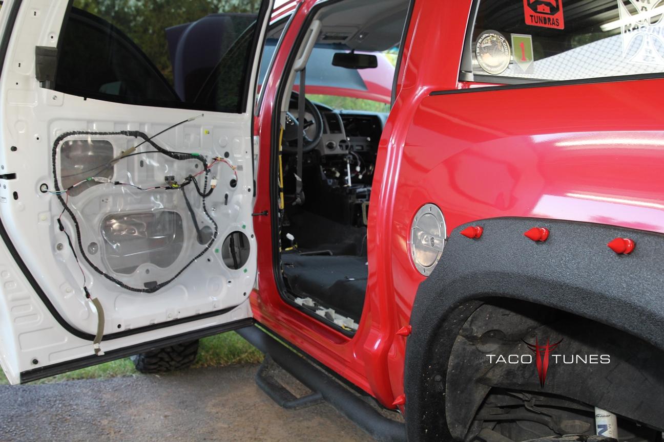
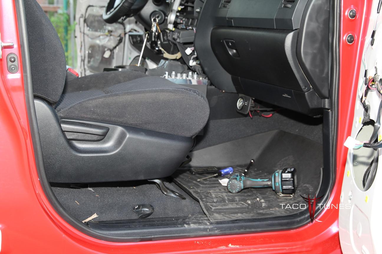
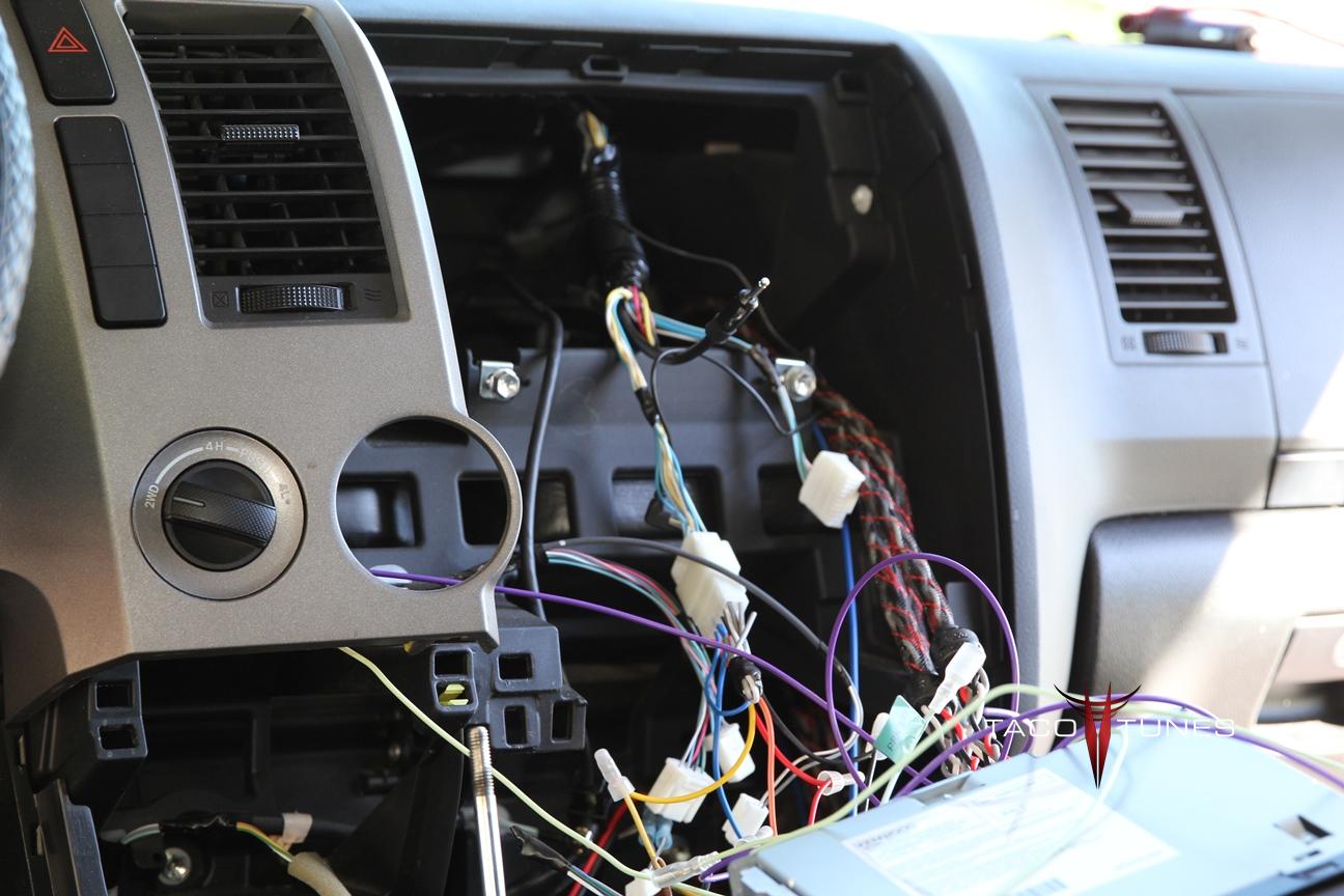
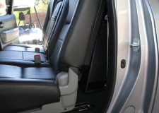
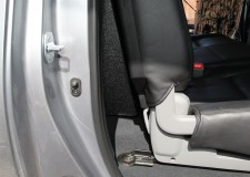
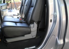
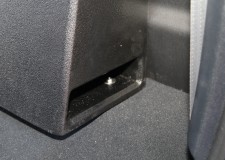
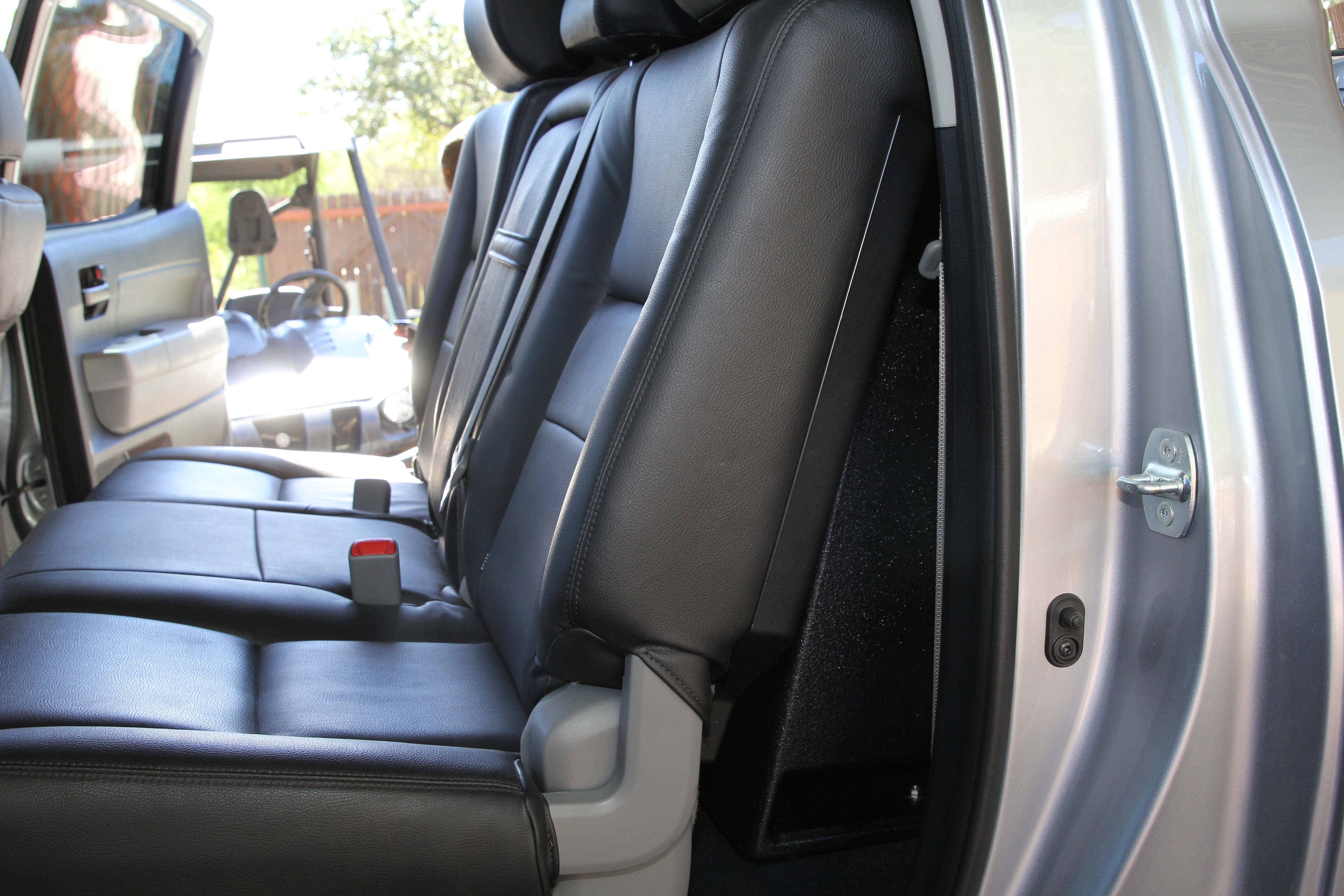
In the 2014+ Toyota Tundra(s), Toyota moved the power source for the front and rear speakers to an external power source located under the passenger seat.
Simply unplug the two harnesses that plug into that small power source. The ReCurve and wiring harness will make the proper adjustments. If you do not unplug the power source, the head unit will not send the signal to the ReCurve.
After removing the two plugs from the power source continue the installation as demonstrated in video.
Should I add capacitor or upgrade the battery if I add amp or upgrade my audio system?
Should I add capacitor or upgrade the battery if I add amp or upgrade my audio system?
Should I add capacitor or upgrade the battery if I add amp or upgrade my audio system? Well this is a very common question we get from our many customers. Keep in mind you will get many different opinions on this topic. Each scenario is different and some of the suggestions may or may not apply in your particular scenario. This write up is for the majority of Toyota Tundra owners. We have installed and assisted in installing THOUSANDS of audio system for our customer base. AT the time of this article we have 23,000 customers and have fulfilled over 32,000 online orders. Plus we install MANY audio systems here in the San Antonio TX area. We have people come from other states to have audio systems installed. We had a vehicles shipped to our shop from as far as Puerto Rico. We also perform aftermarket stereo installations for local Toyota dealers here San Antonio. So, to say we have a lot of experience with Toyota’s is a bit of an understatement. If you have a cousin or friend of friend that disagrees then by all means, please go with their suggestions.
The short answer; for the vast majority of audio system upgrades, you will NOT want or need a capacitor. However, you will want to strongly consider upgrading your stock battery. I have read so many crazy posts over the years, I hope to try to cover as much information on battery selection and the NON use of a capacitor. Personally, I have built and install hundreds of audio systems under 2,000 watts RMS, 4 systems yielding over 12,000 watts RMS in some of my show cars and even in my boat. Not one of those systems required a capacitor. When you properly power and equally as important ground a vehicle, you will notice an increase in sound quality and avoid dimming lights form a higher powered system.
Batteries are like vehicles you need to choose the right battery for your particular needs. So many people will chime in about which battery is best without a clue about batteries. . To many people are fooled by CCA or Reserve capacity but these numbers rarely give the actual load capacity of the battery. So before you purchase a battery or spend a ton of money on something you don’t need. Start with following questions: 1. Do I need a battery that can take heavy abuse? (occasional off-roading hardly requires a “tough” battery) 2. Do I need a battery that provides a long run time with the engine shutoff? For example you tailgate with high powered stereo cranked up for hours. 3. Do you use a winch regularly? There are a few other questions, but do not relate to most folks . . So before you spend a lot of money or time on something you don’t need, do a little homework.
If the answer is no to above questions, just save your money and get a decent battery with a good warranty. If the answer is yes, then you need to narrow down do I need a battery than can take abuse or run time? Which is more important?
A major problem is many manufacturers will use different calculations to rate their reserve & Ah hour rating. So you need to be sure and read the fine print.
In my rock crawler I use an Optima yellow top because it is a dual purpose battery that can take abuse. It has a decent Ah rating and a great starting power. Since I winch a lot and I need to use it to start the crawler every time I manage to kill it, that battery works great.
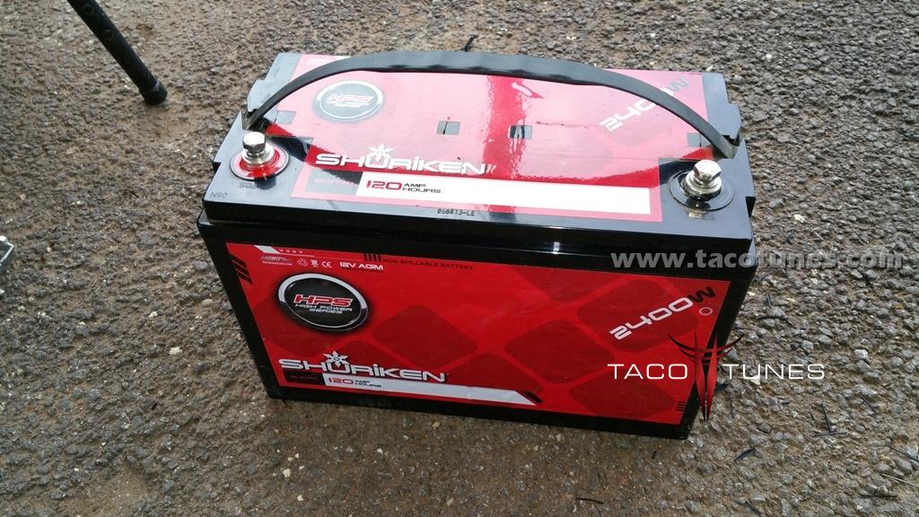
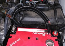
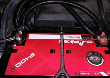
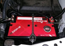
In Tundras – with audio systems, I like use the Shuriken AGM 120Ah battery. It can take some abuse, but this battery has over 45Ah more run time than the heftiest yellow top (at time of this post). It does great with a winch (only use occasionally) and I can tailgate with my loud stereo for much longer play time.
Check out this post for step by step instructions on how to install an AGM battery into your Toyota Tundra. Note, we have done this same upgrade on Toyota Tundras ranging from 2007 – 2015. NOTE: We have only done this on Tundra’s equipped with a 5.7 liter engine.
Ok, so why did I choose Shuriken? Well after years of trying different batteries and REAL world testing, the Shuriken has an amazing bang for buck. We have a show truck we use car shows. The truck is crazy loud and can run for up to 8 hours with 3 Shuriken 120BTs. WE had a couple of other brand batteries that we pulled out over time testing. Additionally, my personal boat has over 5,000 watts RMS and I rely on my batteries to play ALL day when we are tied up in the party cove entertaining all the crazy girls dancing! What good is a battery if it can’t hang longer than the party?
Some other issues to ponder:
Will the battery fit?
Are the terminals in the correct spot?
Will I need to change my battery connectors?
Will I need to modify my battery tie down?
Plus quite a few others . .
Battery Types:
Wet Cell (Flooded) – This is the average basic battery installed by auto manufacturers and the most popular replacement battery you will pick up at your local parts store. There are two types to choose from serviceable and sealed.
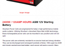
AGM – Absorbed Glass Matt are constructed of suspended plates that are in close proximity with very little liquid and can be mounted in just about any position. Common applications include high performance engine starting, power sports, deep cycle, solar and long term storage battery. The larger AGM batteries are typically good deep cycle batteries and they deliver their best life performance if recharged before allowed to drop below the 50% discharge rate. When Deep Cycle AGM batteries are discharged to a rate of no less than 60% the cycle life will yield hundreds of deep cycles. They are dual purpose batteries. You can use them to start your application and provide a deep cycle that will ruin standard wet cell batteries.
Gel Cell – The Gel Cell is similar to the AGM style because the electrolyte is suspended, but different because technically the AGM battery is still considered to be a wet cell. The electrolyte in a Gel Cell has a silica additive that causes it to set up or stiffen. Gel Batteries are best used in VERY DEEP cycle application and may last a bit longer in southern regions where heat is a batteries major enemy.
Battery Comparison:
At the time of this post, below is a picture and specs for the the following batteries.
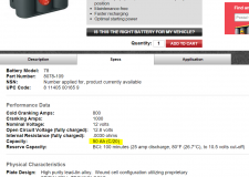
Yellow Top – 8051-160
Ah: 75 (C/20)
Weight: 59.8 lbs
CCA:900
Red Top – 8078-109
Ah: 50 (C/20)
Weight: 39.5 lbs
CCA:800
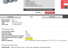
Shuriken SK-BT120
Ah: 120 (C/20)
Weight: 79 lbs
CCA:920
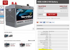
Northstar NSB-AGM-31M
AH: 102 (C/20)
Weight: 76 lbs
CCA:900
As you can see in the specs provided by each manufacturer. The Shuriken edges out all the batteries in run time. However as stated above, you need to choose the right battery. We use the Shuriken BT-120 in Toyota Tundras and Tacomas. They will fit into the truck with some modifications. I personally use the yellow top in my rock crawler because the battery is made for heavy physical abuse. Most Toyota Tundra and Tacoma owners are not going to abuse their truck at the level of a rock crawler. Northstar makes a great battery and they are very expensive. However, they have a better warranty than the Shuriken BT-120 1 year warranty. I am obviously biased towards the Shuriken. I have been using them for over 5 years in my boat. The same 3 batteries run my 5,000 watt (RMS) system all day long! What good is a great stereo with a battery that can’t hang?
Do I need to do the Big 3?
First off some of you guys are probably asking what is the Big 3 (see below)? Over the years, most car audio guys have probably heard about the big 3 upgrade. This upgrade stems from the OLD days when Chevy & Ford STOCK alternators had a max amperage output of roughly 50 amps. Times have changed along with power requirements. For example, if your 2007+ Toyota Tundra has the tow package, you probably have 150 amp alternator. Cars these days have way more electronics and require a lot more power than the “old days”. So unless you are building a CRAZY system, you only need to upgrade your chassis ground in your Tundra. Check out our how to page here. If you purchase a battery similar to our recommendations above, you will not need a capacitor.
What is the Big 3?
Larger gauge power wire from alternator positive to battery positive, Larger battery wire negative to chassis, and larger engine ground wire to chassis
Click here to see how to upgrade the battery in your Toyota Tundra.
How to install upgrade select battery and upgrade your stock chassis ground for better power flow.
How to install upgrade select battery and upgrade your stock chassis ground for better power flow in your Toyota Tundra.
How to install upgrade select battery and upgrade your stock chassis ground for better power flow in your Toyota Tundra. Don’t waste your money on a capacitor.
Below we have performed a battery upgrade to assist with the additional power requirements from a higher end stereo system. If you would like to see more info on selecting batteries and understand why we chose this battery please visit the post – How to select a battery for your Toyota Tundra . For the record, the best route for doing this type of upgrade is using copper crimps and solder. However, many will not have the tools or have the knowledge to e able to crimp and solder heavy gauge wiring. We have field tested this setup on a number of Toyota Tundras with great results.
If you are interested, we offer this kit along with a battery in a bundled kit. The terminals will be pre-crimped and heat shrunk, you will need cable cutters, Allen wrenches & socket set to complete installation.
In the write up we will take you through upgrading the stock wet cell battery to a high quality AGM battery.
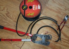
The parts we used in this upgrade are as follows:
Positive Side:
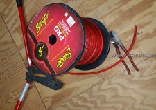
2 – 4 gauge 16″ Stinger Cable – Red
2 – 4 gauge copper battery ring terminals
2 – battery cable splicers (non soldering)
2 – 4 gauge 2″ marine grade heat shrink with sealing glue
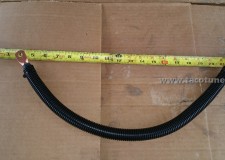
1 – 7 feet 1/2″ split loom
1 – 3 feet 3/4″ split loom
20 – zip ties
Negative Side:
1 – battery cable ring terminal (non soldering)
1 – 1/0 Gauge 24″ Stinger Power Cable – Black
2 – 1/0 Gauge copper battery terminals
1 – 2 feet 3/4″ split loom
1 – 1 foot 1/2″ split loom
Tools Used:
Large crimping tool
Large cable cutters
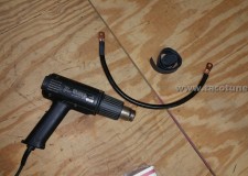
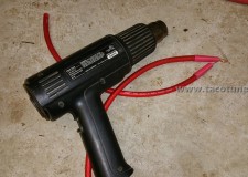
Heat Gun
Allen Wrenches
Metric Socket Set
Battery:
Shuriken 120BT


TEXT:
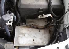
Picture of Toyota Tundra with stock battery removed.
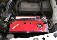
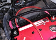
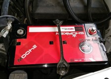
We will be installing the Shuriken BT120 AGM battery. Be sure to check out our “how to select a battery for your Tundra”!
The stock battery has been removed. Here you can see the positive and negative terminals disconnected from the battery.
To avoid any confusion, we will focus on the negative terminals first. It is crucial you do not mix up your cables. Serious damage or injury can occur.
Cut off the negative battery wire as close as you can to the terminal. Try to avoid cutting the terminal, it might damage your cable / wire cutters.
We will be upgrading the chassis ground with a 1/0 cable – roughly 4 times thicker / heavier than the stock 8 gauge (roughly) stock cable.
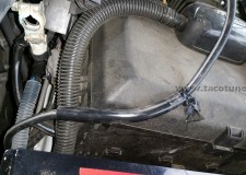
The negative chassis ground cable has been removed. We are test fitting the battery to ensure proper length of the negative cable we will be adjusting to work with the new battery. NOTE: The battery terminals will be opposite of the stock location.
Remove the black tape and extra cover shown on the negative cable. We will be covering this wire with split loom.
Be sure to leave a little extra cable to work with.
Using your cable cutters or a razor carefully remove around 1” inch of the insulation. For best results be sure to measure it against the new negative terminal.
Insert the exposed cable into the negative terminal as shown. Then using an allen wrench be sure to tighten the locking screw.
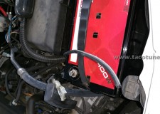
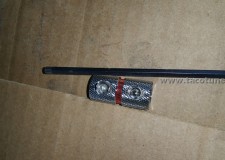
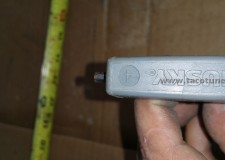
Next we will manufacture the replacement / upgraded chassis ground. In the picture you can see the 1/0 cable next to 4 gauge cable. We are using copper battery terminals sized for your Toyota Tundra. Using the monster crimpers, we will permanently attach the battery terminals to the cable.
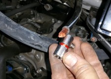
Using a heat gun we will apply marine grade heat shrink that contains a sealing agent.
After sealing the connections, we will cover the cable in split loom and zip tie the ends.
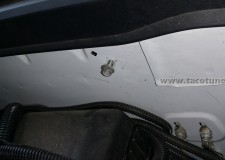
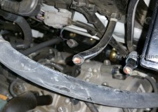
In this step we will remove enough paint and primer to ensure proper conductivity between the new chassis cable and battery.
Using sandpaper remove paint to expose metal to ensure a good ground.
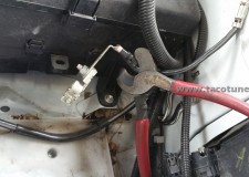
Install the new chassis ground as shown. DO NOT ATTACH TO BATTERY UNTIL ALL STEPS COMPLETED. Connect the GROUND wires to the battery last! You may want to label the wires to ensure you do not mix them up.
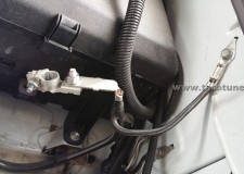
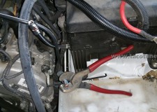
Remove the positive battery terminal from the positive battery wires by removing the bolt.
Picture of the stock wires with the battery terminal removed.
Cut the wires as closely to the connectors. You will also need to remove some of the loom to gain access to the wire as shown.
Here you can see the solderless splice. Strip away enough of the insulation to go half way into the splice.
If you are purchasing one of our kits you do not need to test fit the battery. With the battery removed you will strip away the insulation as shown.
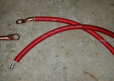
In this step we are going to manufacture the positive cable wire extensions. Here you can see the battery terminals, heat shrink and 4 gauge wiring.
Picture of 4 gauge wiring & terminals
Picture of 4 crimped terminals and marine grade heat shrinking with sealing agent.
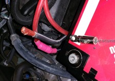
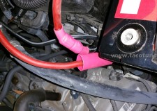
Attach the positive wire extension to the splicing kit. Be sure to tighten, wiggle cables and then tighten again.
After you have tightened both splice kits, you will use your heat gun to heat the marine grade heat shrink. Be sure the heatshrink is HEAVY duty. If you are using a lower quality heatshrink, you will want to cover the heat shrink with electrical tape to ensure the cables are properly protected from accidental grounding.
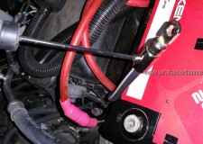
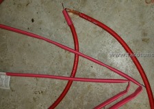
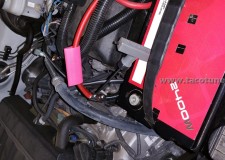
Picture of the positive cables ready for split loom.
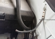
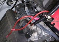
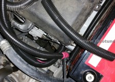
Install the ½” split loom on the upper part of the cable as shown. Then install the ¾” split loom on the lower half of the cable. Using the zip ties ensure the split loom will stay in place.
The lower part of cable & splicer will require
The stock battery tie down kit will work, but you will need to “wrestle” with it a little to get it installed.
Remove the stock tray before installing the battery.
Not shown in this picture, wrap black electrical tape around the splicer. This will ensure you have multiple layers of protection.
DLS Component Speakers RS6.2 – Toyota Tundra
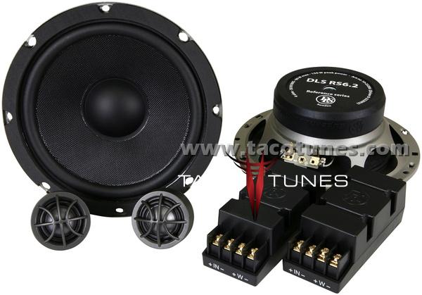
Toyota DLS Component Speakers R26.2 Component Speakers
To install DLS Component Speakers RS6.2 Component Speakers into your Toyota, you will want to use tacotunes.com speaker adapters designed to work in your Tacoma. The DLS Component Speakers RS6.2 Component Speakers require a 5.8” cutout diameter for the mid range speakers. The DLS Component Speakers RS6.2 Component Speakers tweeters will require a 1.81″ cutout diameter.
Click HERE to check out our audio products for your Toyota Tundra
The Polk Audio db6501 Component Speakers will fit you your Toyota Tacoma without any cutting, drilling or modifying your Tacoma.
Summary:
Mid range Driver: 5.8” cutout diameter
Tweeter: 1.81″ cutout diameter
Top Mount Depth: 2.09″
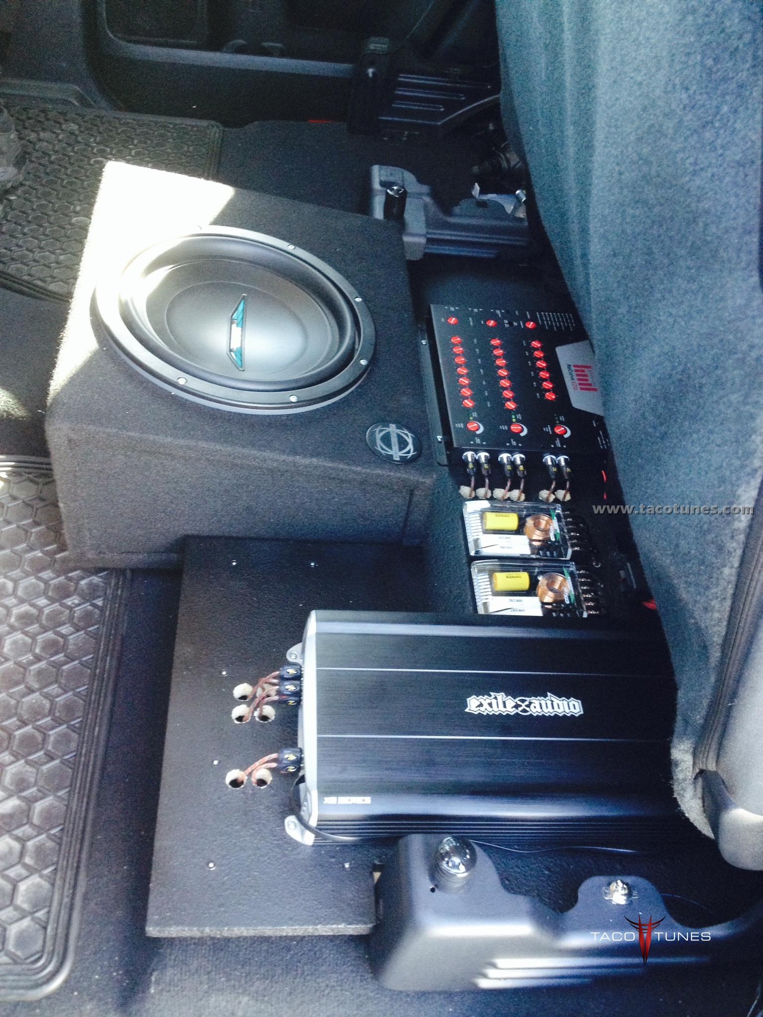
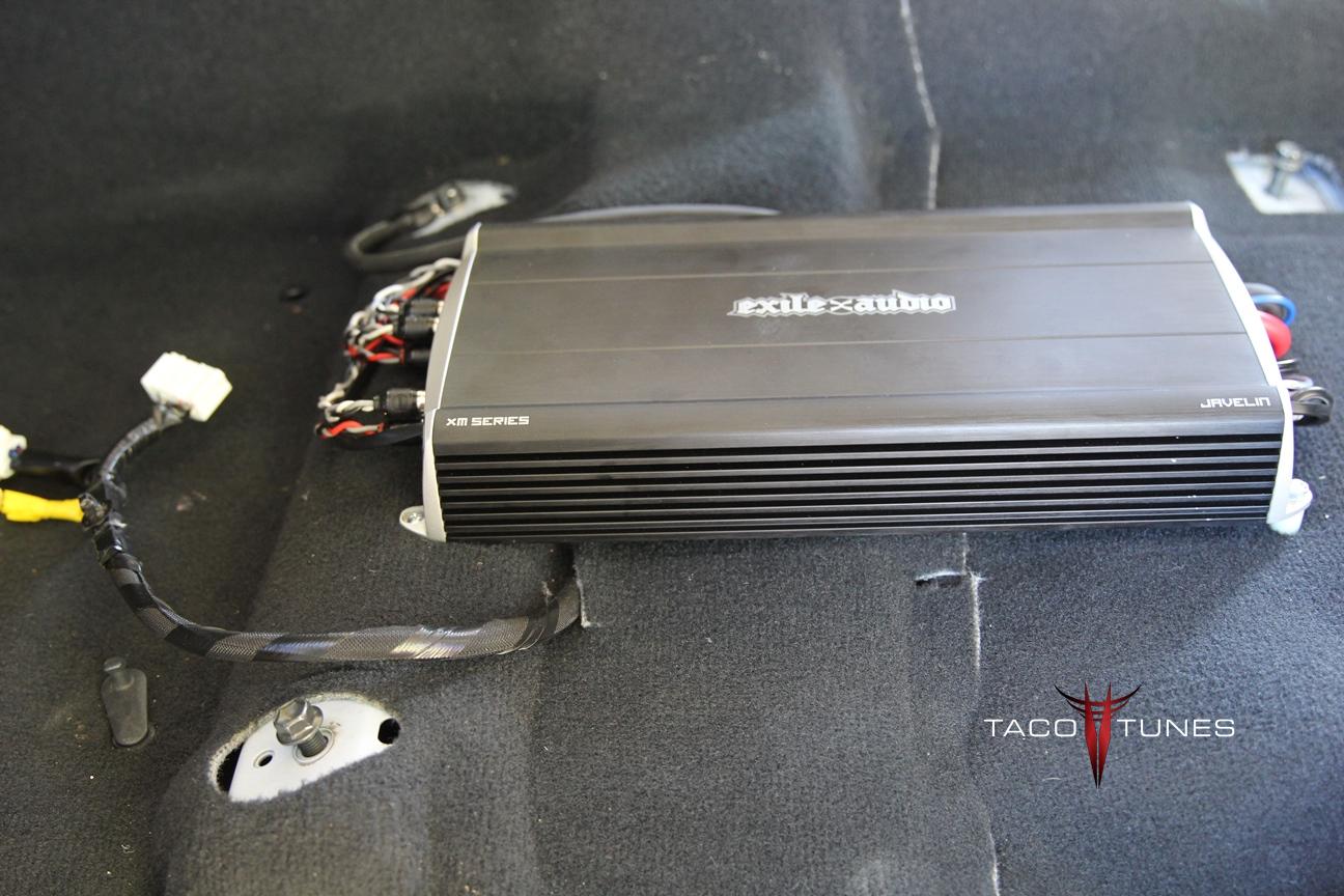
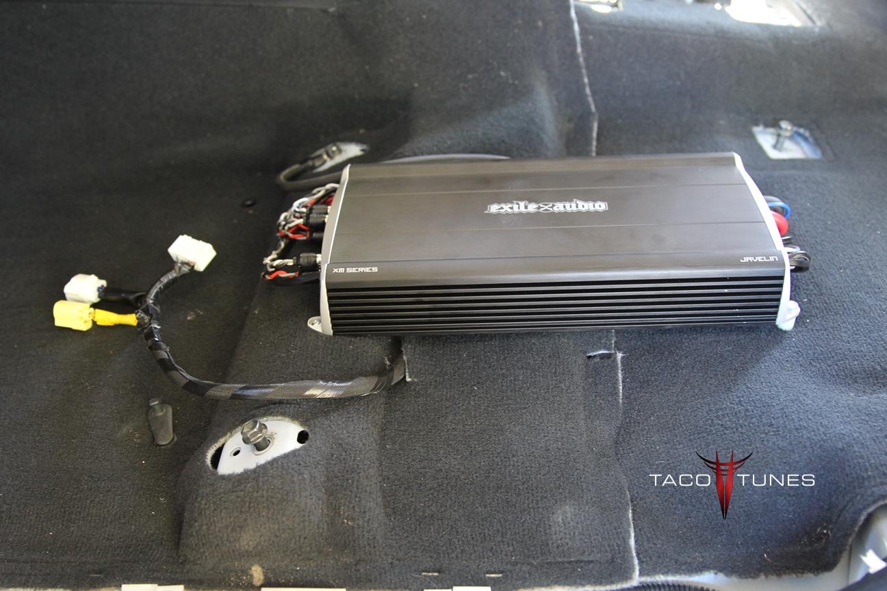
Exile Audio Javelin 5 Channel Amplifier
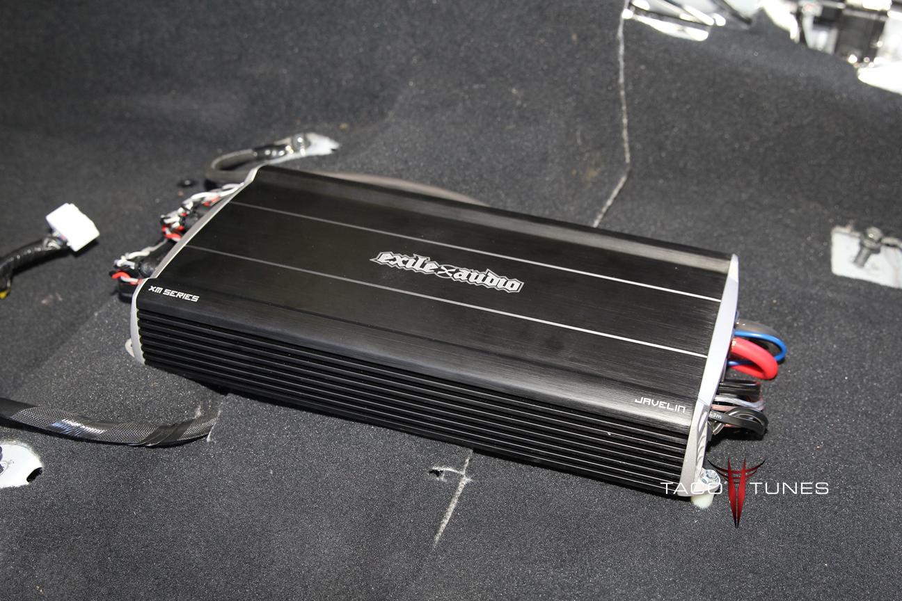
Exile Audio Javelin 5 Channel Amplifier
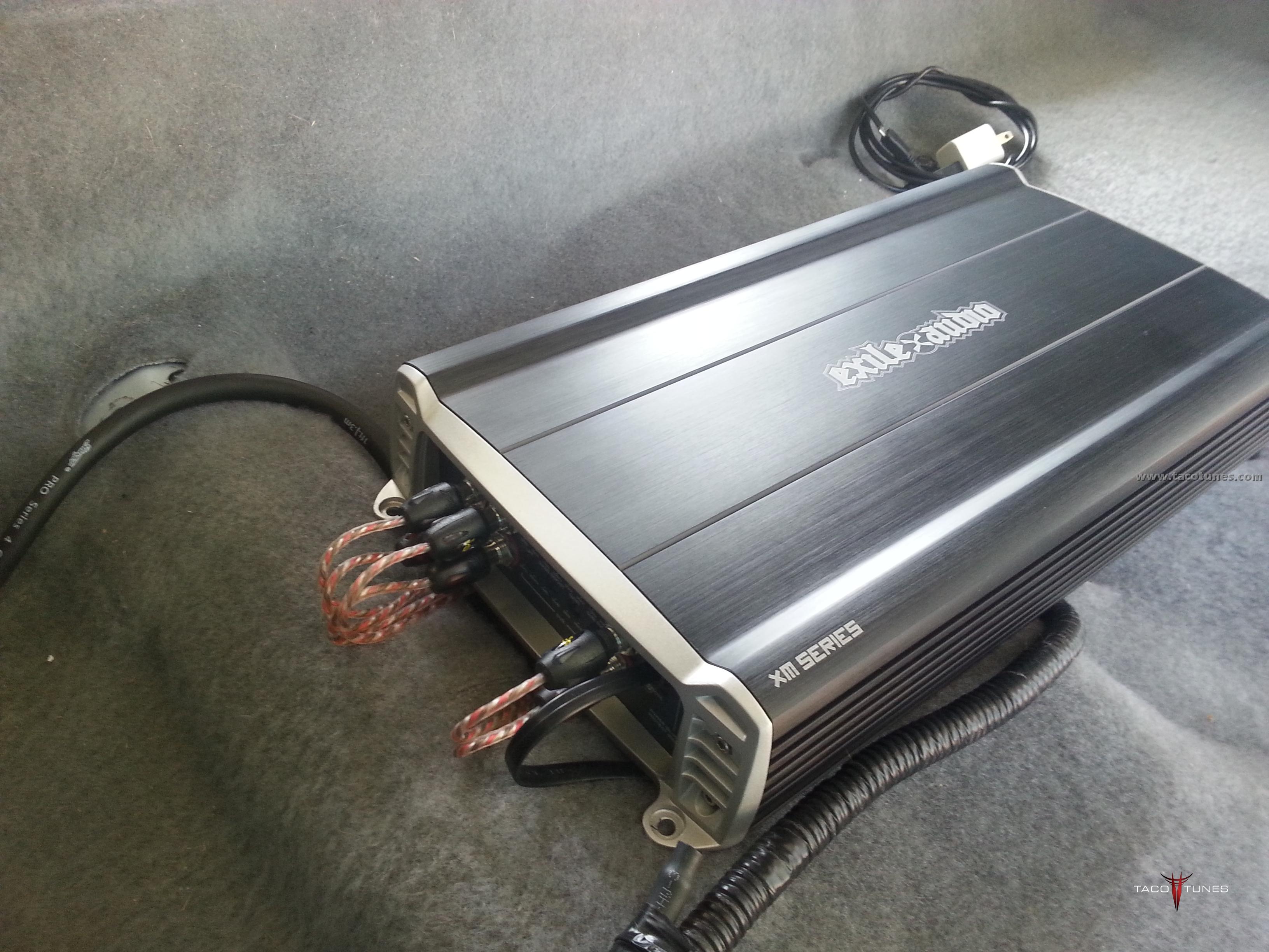
Exile Audio Javelin 5 Channel Amplifier Big Power.. Small footprint. The Javelin amplifier will provide 4 x100 watts to your front / rear door speakers. It will also provide up to 800 watts to your subwoofer(s). Originally designed for a harsh marine environment we began installing these for our customers as tougher solution for our hard core offroaders. They quickly became popular with our customer base.
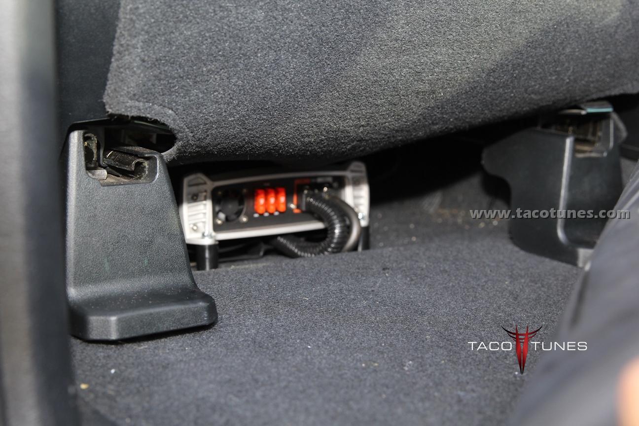
In most cases we recommend the amp to be installed under the driver seat. The stainless steel hardware and epoxy coated circuit boards have proven to be a valuable asset for some of our toughest customers.
Combine the rugged amp with amazing sound quality and you end up with an amplifier solution that is difficult to match.
Be sure to check out our installation kit for your Toyota AND be sure to ask about bundled pricing with our turn key packages.
Exile Audio Amp installed in 2014 Toyota Tundra
Exile Audio Javelin Amp installed in 2010 Toyota Tundra
Exile Audio Javelin Amp Installed in 2011 Toyota Tacoma
Exile Audio Javelin Amp Installed in 2011 Toyota Tacoma
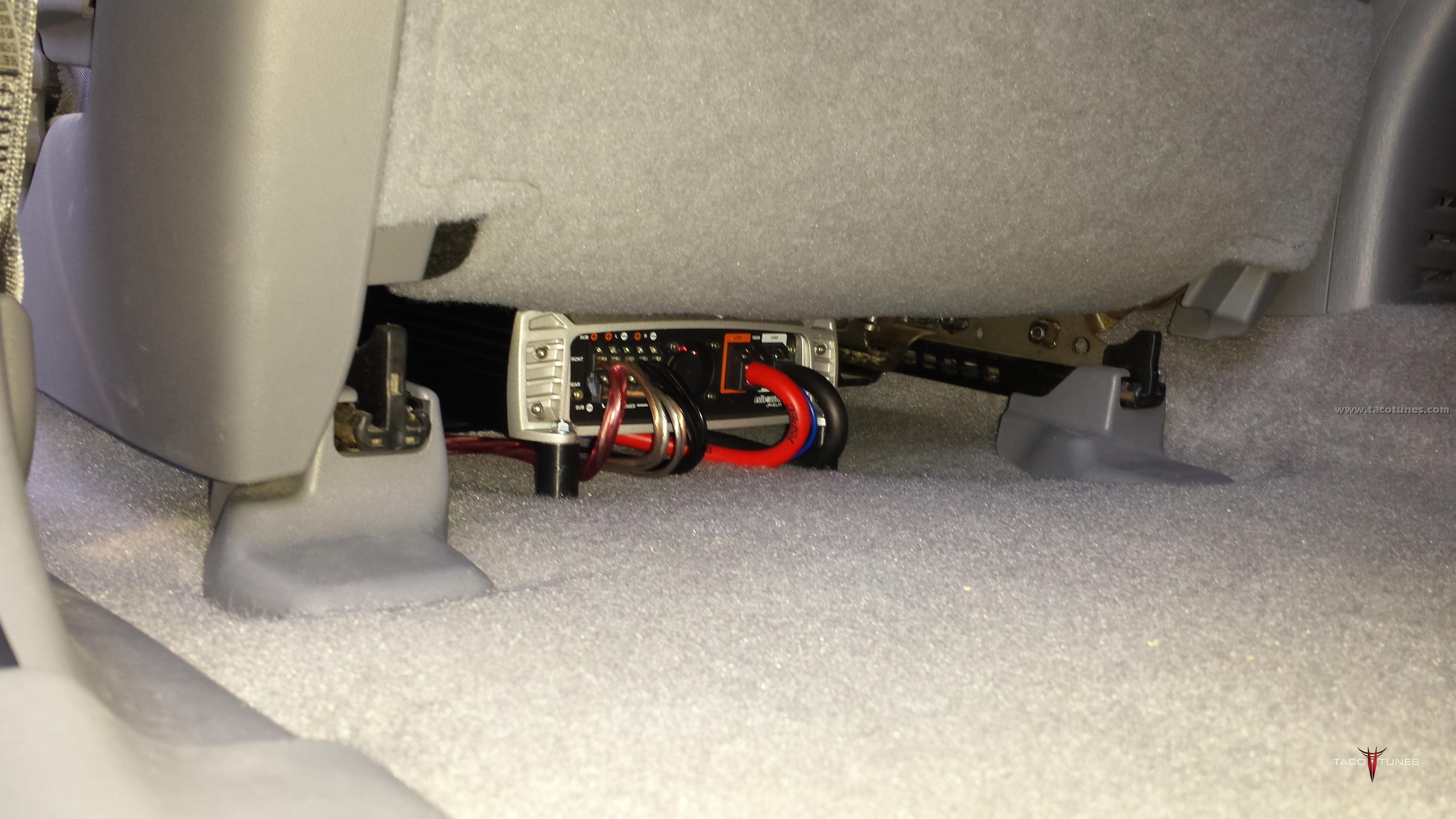
Exile Audio Javelin Amp Installed in 2003 Toyota Tacoma
Power Ratings:
Into 4 ohm: 100w x 4
Into 2 ohm: 150w x 4
Into 4 ohm bridged: 240w x 2
Sub Channel Into 4 ohm: 500w x 1
Sub Channel Into 2 ohm: 800w x 1
Specs:
Dimensions: Length: 15.0in (381mm) x Width: 7.5in (190.5mm) x Height: 2.3in (58.4mm)
Channels: 5
Amplifier Class: Full range class D
Fuse Size: 40A x 3
Recommended Power/Ground Wire: 4 AWG
Total Harmonic Distortion: <0.5%
Signal to Noise Ratio: 92dB
Gain Range: 0.2 – 6V
Low Pass Crossover Range: 50 – 250Hz
Bass Boost: @ 45Hz 0 to +18dB
Operational Efficiency: >85%
Damping Factor: >200
Remote Bass Control: Yes
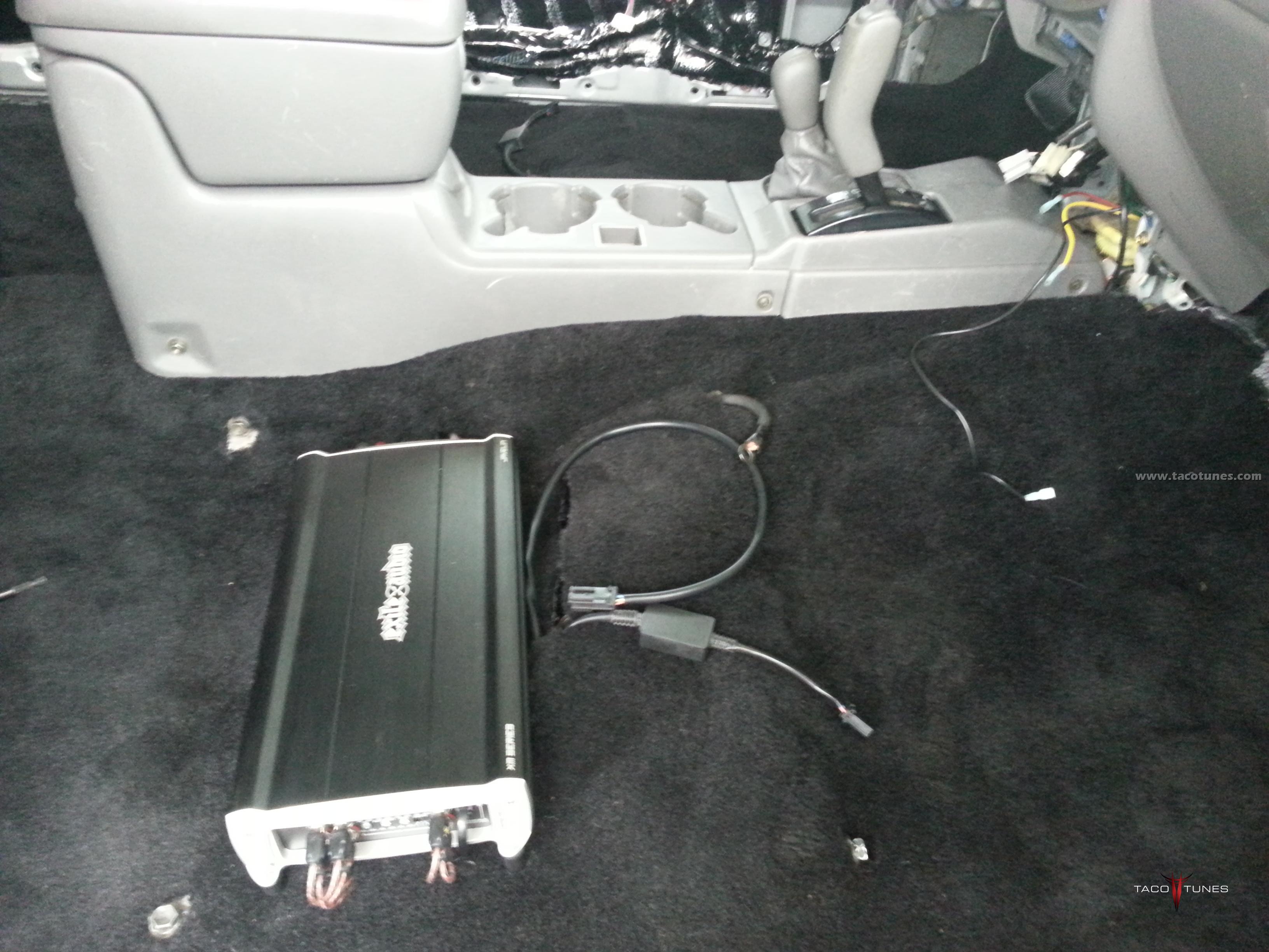
2010 Toyota Tundra Full Stereo System Installation San Antonio Texas
2010 Toyota Tundra Full Stereo System Installation San Antonio Texas
We had the pleasure of installing a system for a local wounded hero here in San Antonio TX. Joe Drozd is also the founder and president of a Texas Toyota Offroaders. Joe came to us after a car show where he saw a few of or demo rides. He said I have to have that!
Joe’s Testimonial.
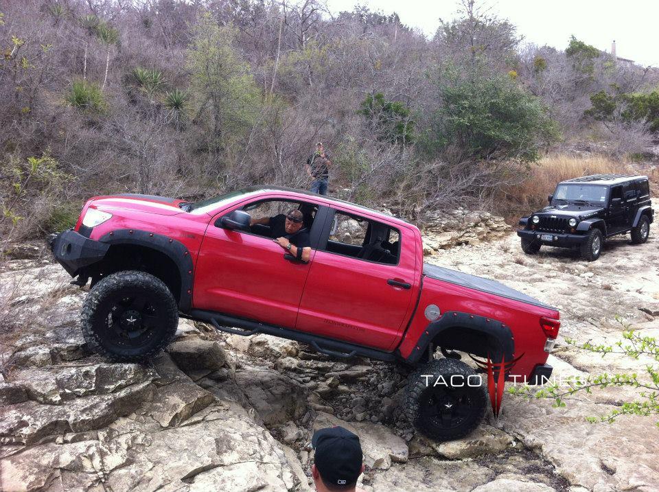
We will break up Joe’s truck into two parts. The first will be installation pics of the stereo system. The second part will be pictures of his Mad Max Toyota Tundra.
Joe’s Stereo System:
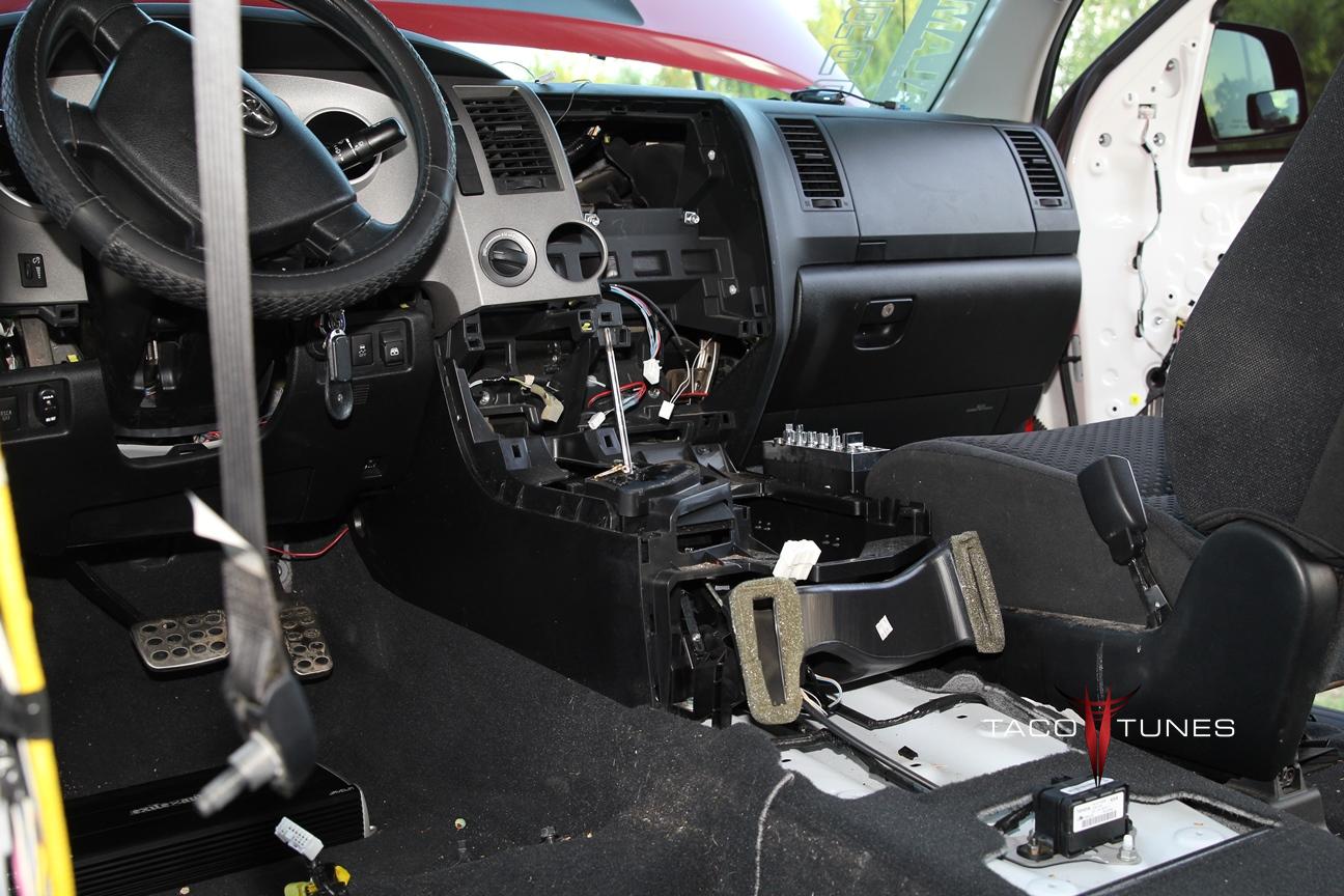
Joe had a basic head unit and wanted to be able to watch DVDs so he upgraded his head unit to Kenwood DVD unit. We supplied all the parts and installed the system over a 2 day period.
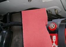
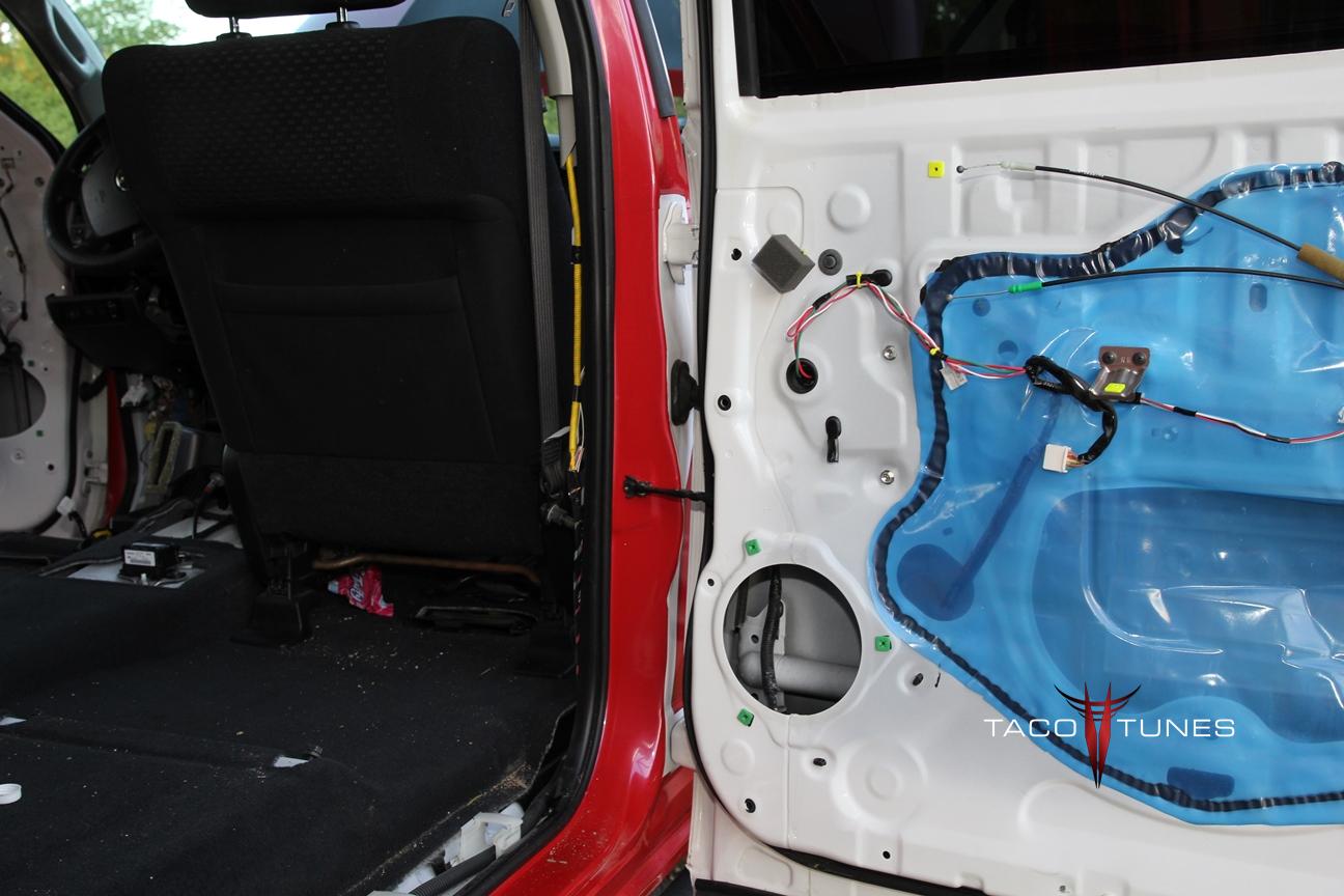
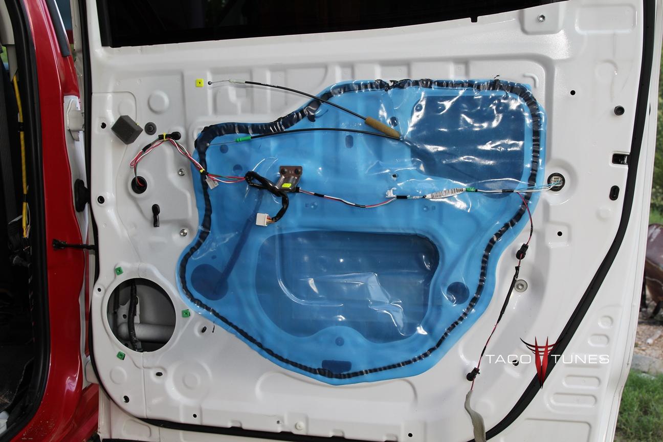
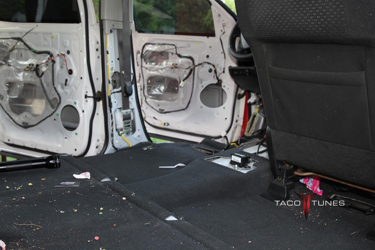
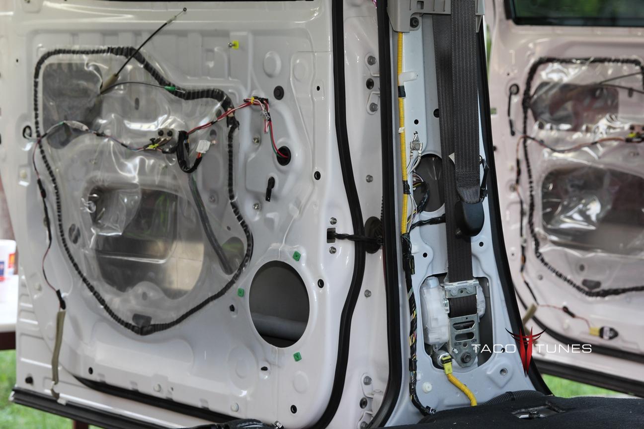
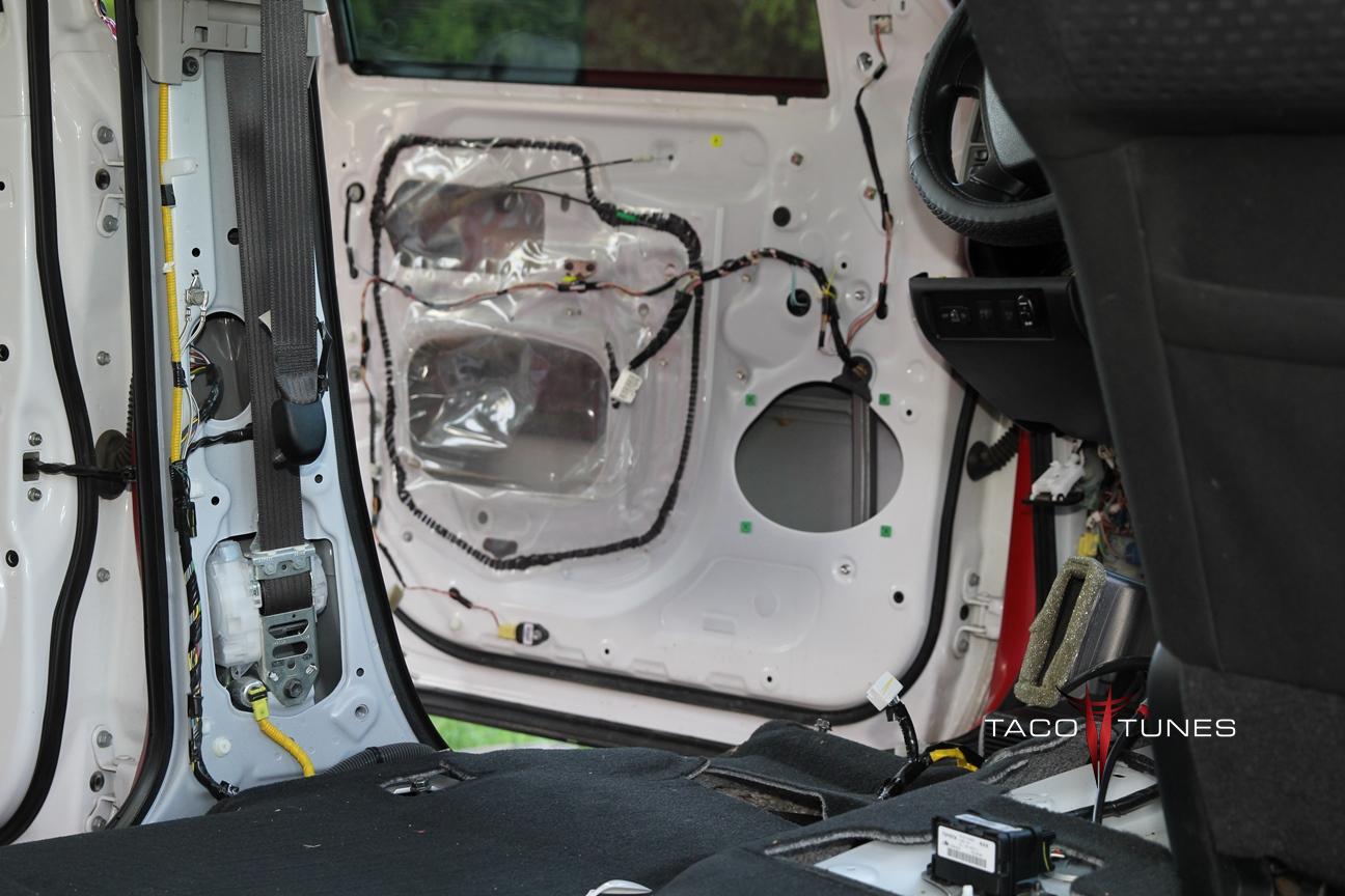
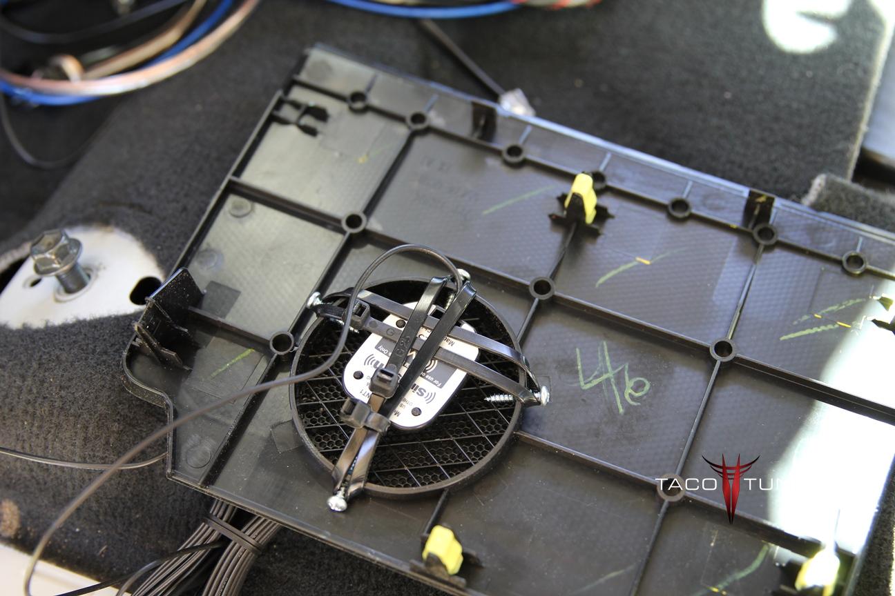
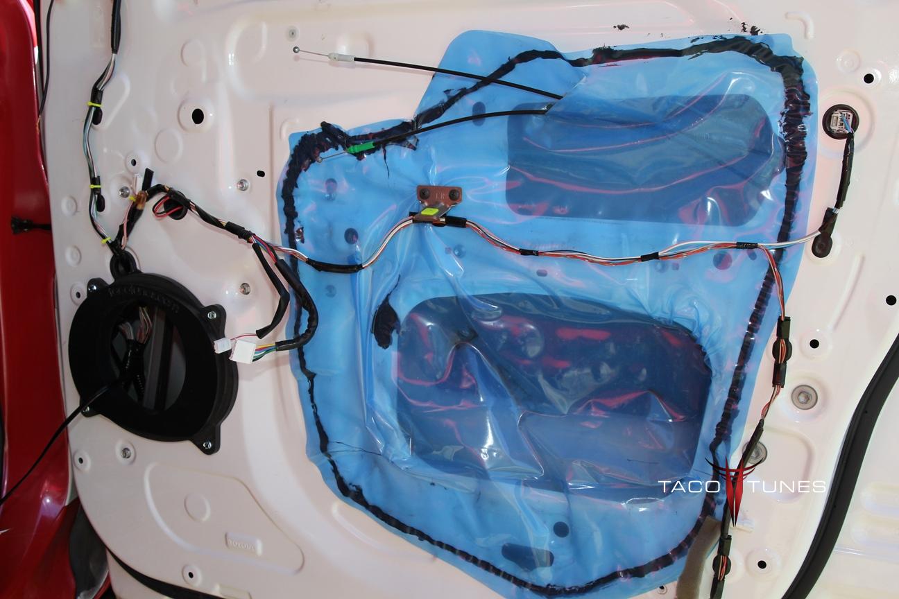
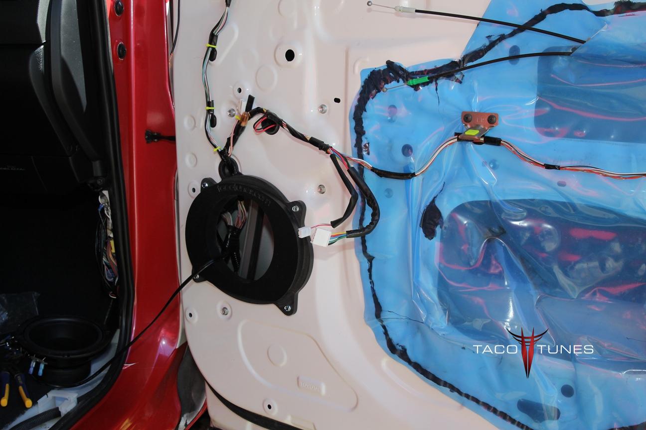
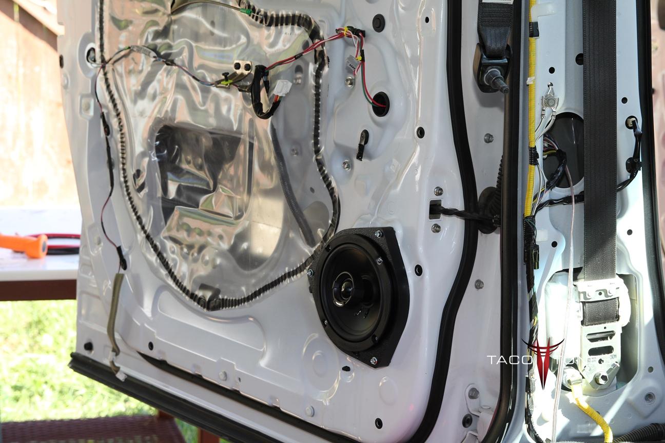
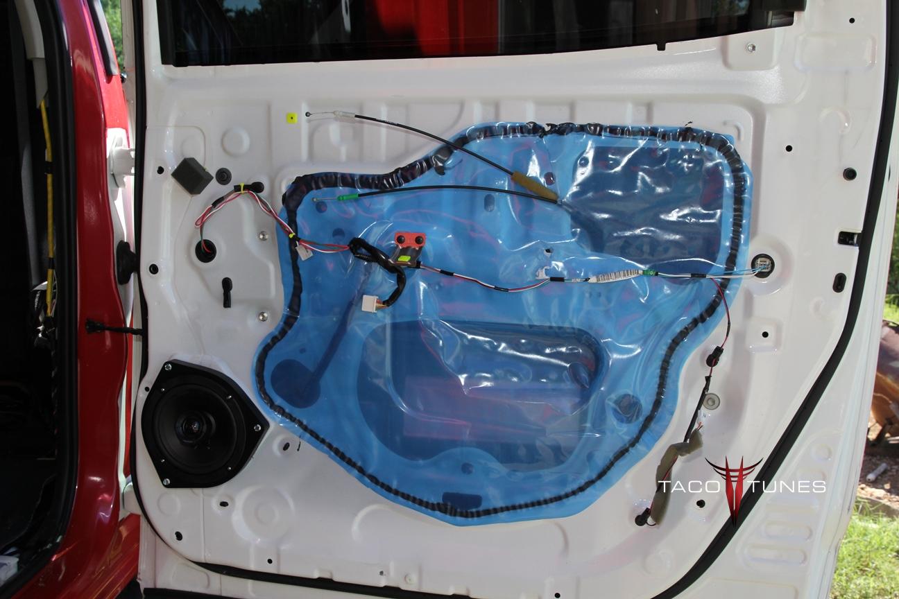
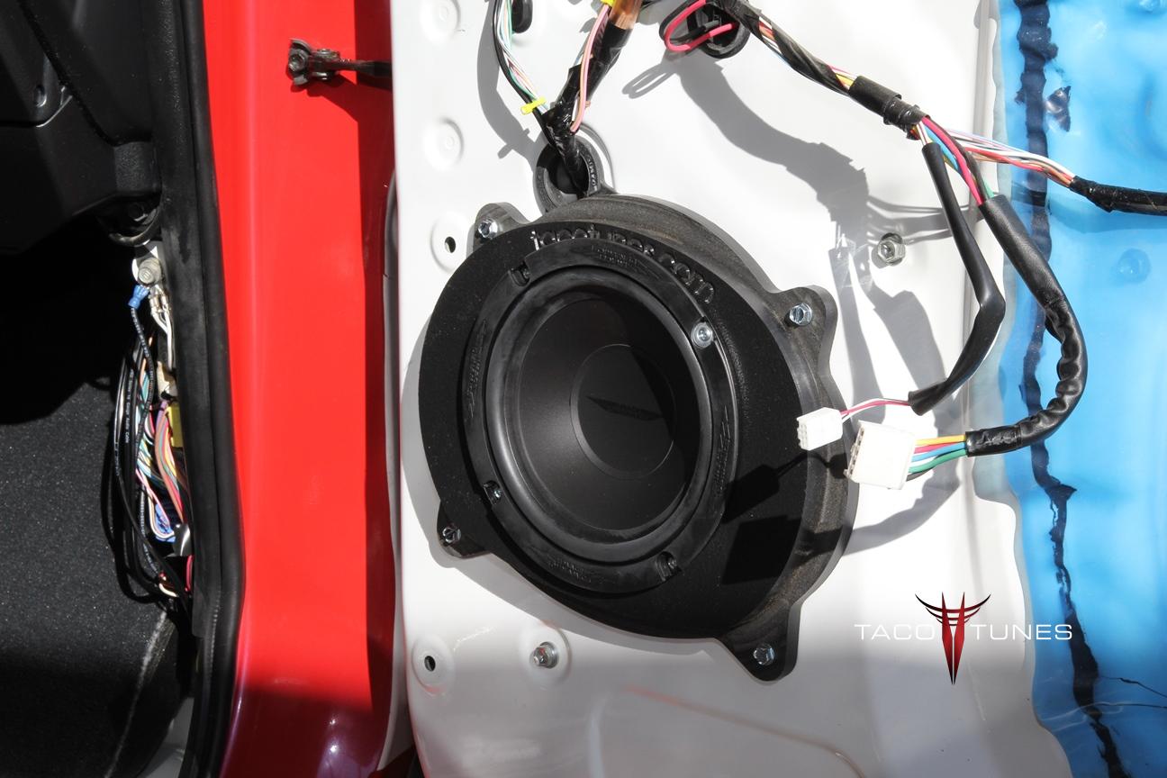
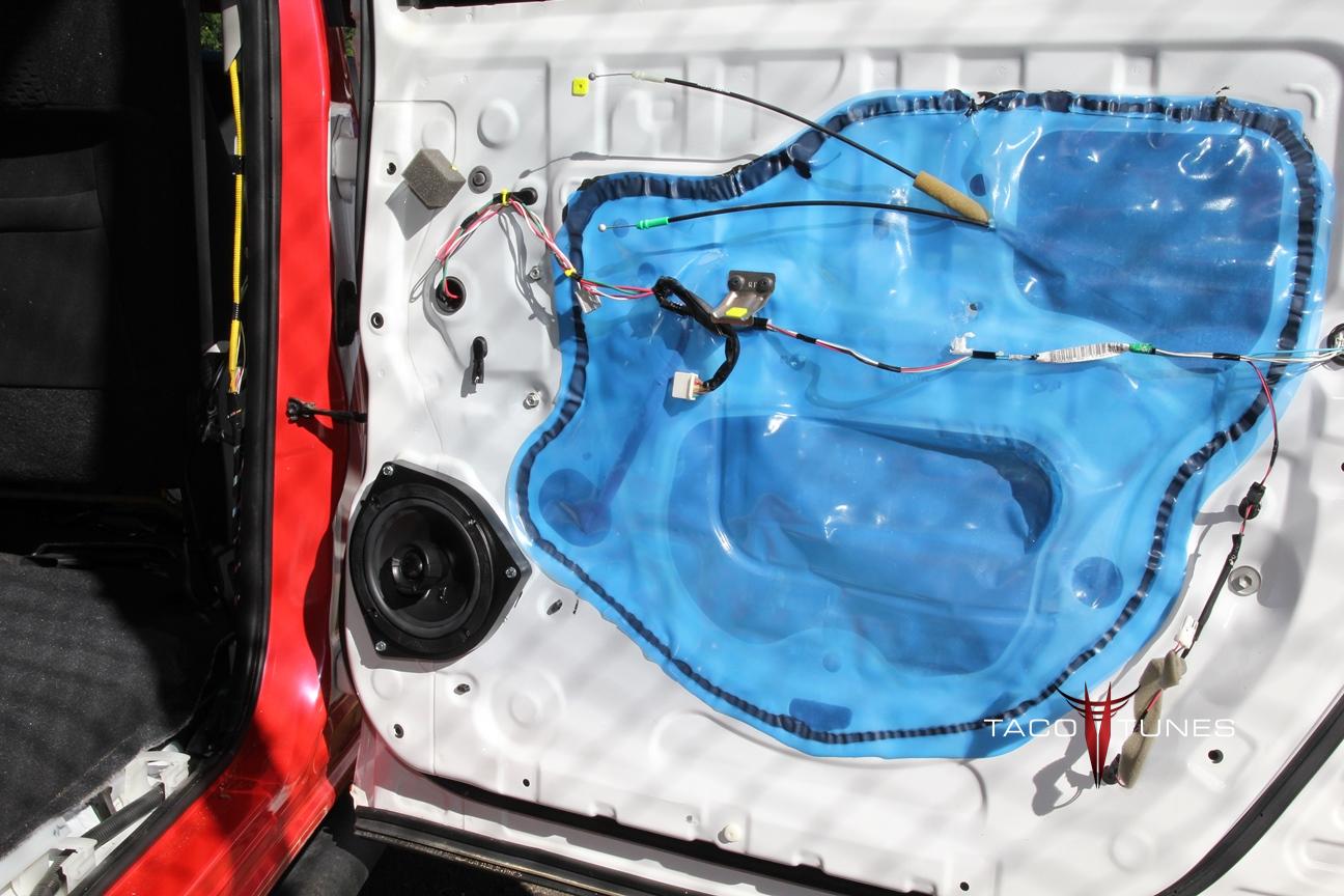
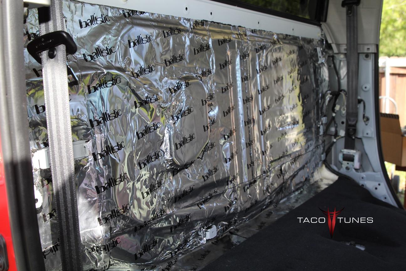
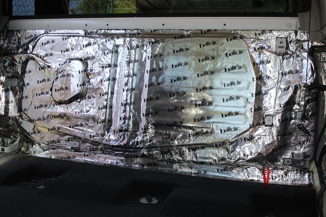
Matting:
First we matted the truck with Ballistic matting. The doors and rear wall was matted to help reduce ambient noise and to eliminate rattles caused by the higher powered speakers and subwoofer. NOTE: Ballistic matting is now black. We also did not take pictures of the matting we installed on doors. We included some examples from another Tundra.
Head Unit:
Kenwood DDX770
Dash Installation Kit
Steering Wheel Interface Kit
Amp:
Exile Javelin 5 Channel Amp 100 watts x 4 (speakers) 800 watts x 1 (subwoofer) RMS
Speakers:
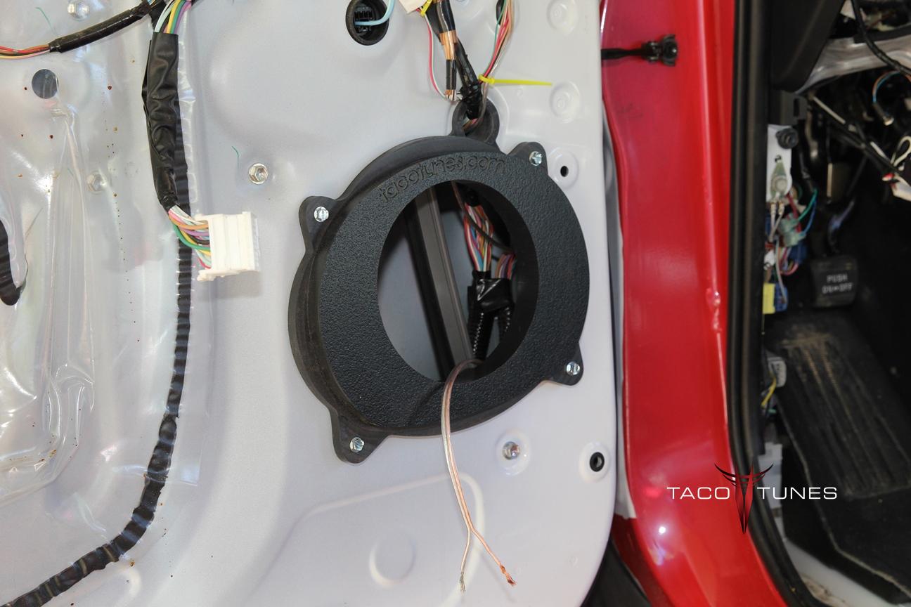
Front Doors: Image Dynamics CTX65CS – Compnent Speakers & tacotunes.com speaker adapters
Rear Doors: Image Dynamics CTX65 – Coxial Speakers @ tacotunes.com speaker adapters
Subwoofer: Image Dynamics IDQ12V4D4
Subwoofer Enclosure: tacotunes.com 12″ port tuned subwoofer enclosure
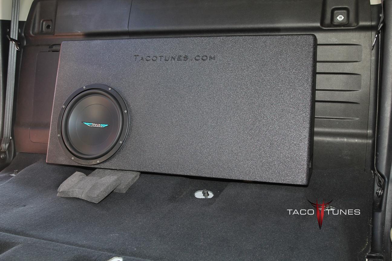
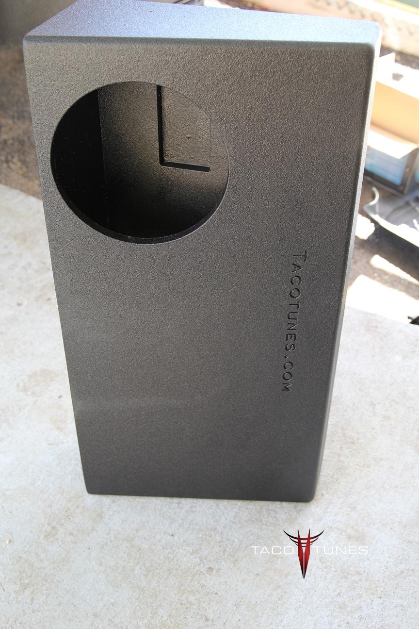


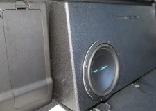
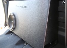
2007-2013 Toyota Tundra CrewMax Ported Subwoofer box enclosure full size subwoofer
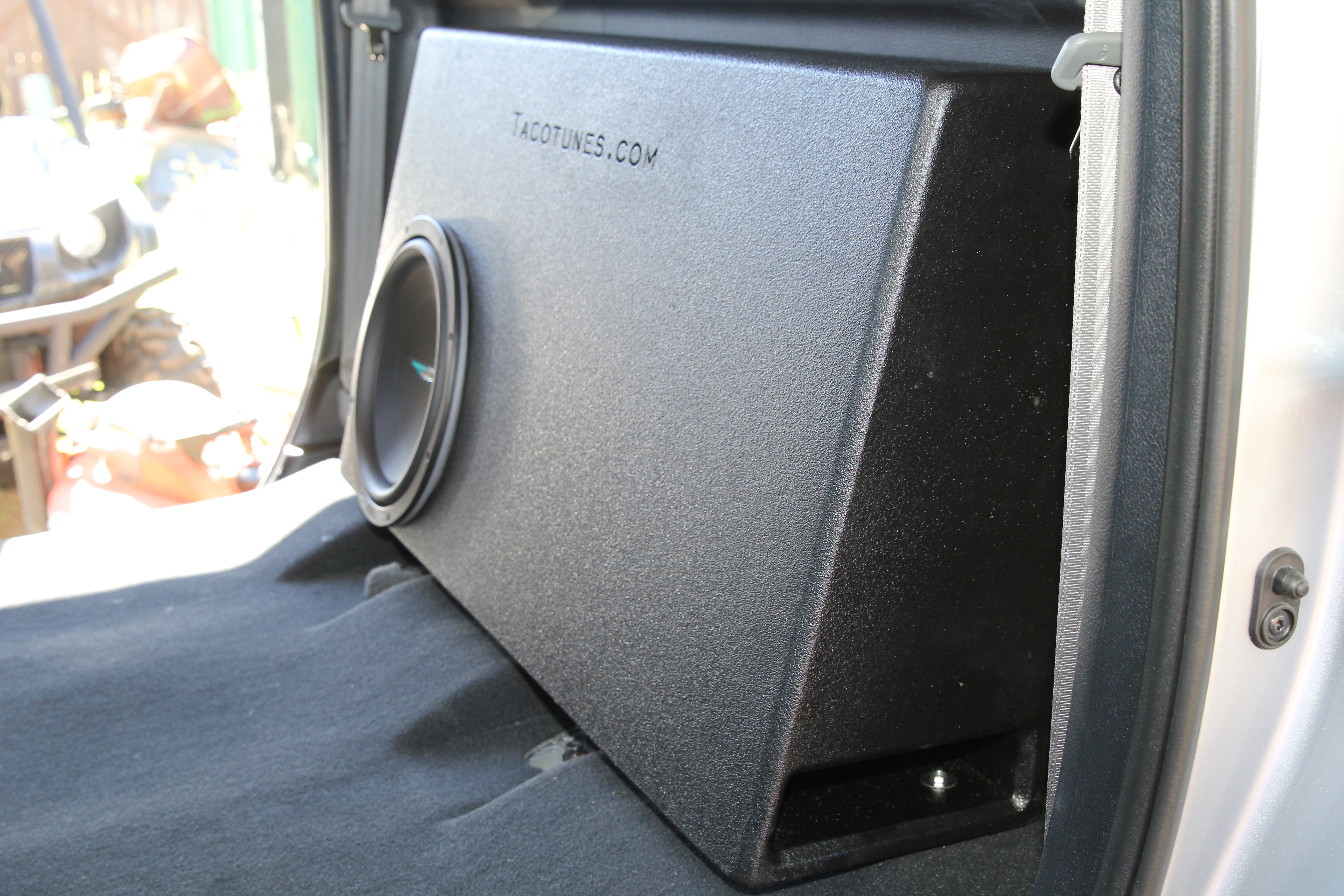
2007-2013 Toyota Tundra CrewMax Ported Subwoofer box enclosure full size subwoofer
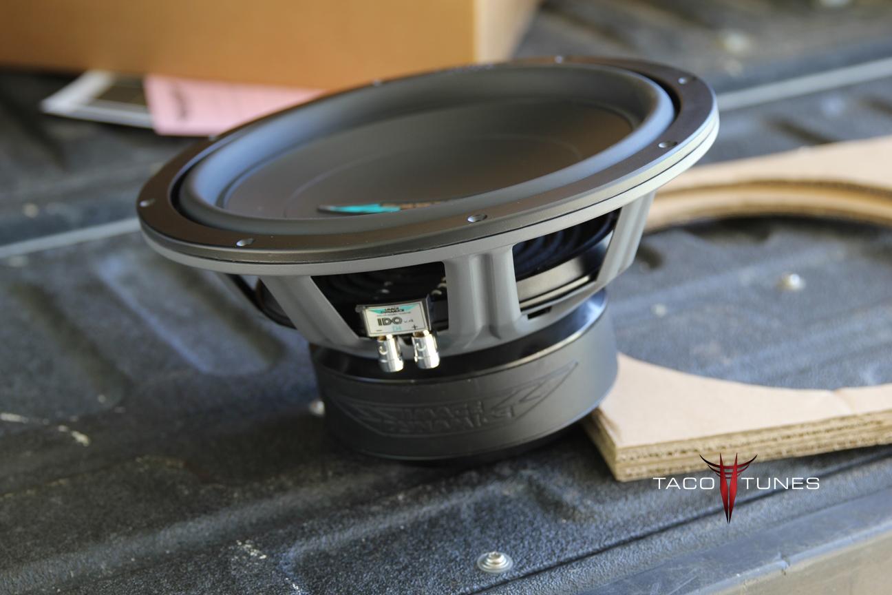
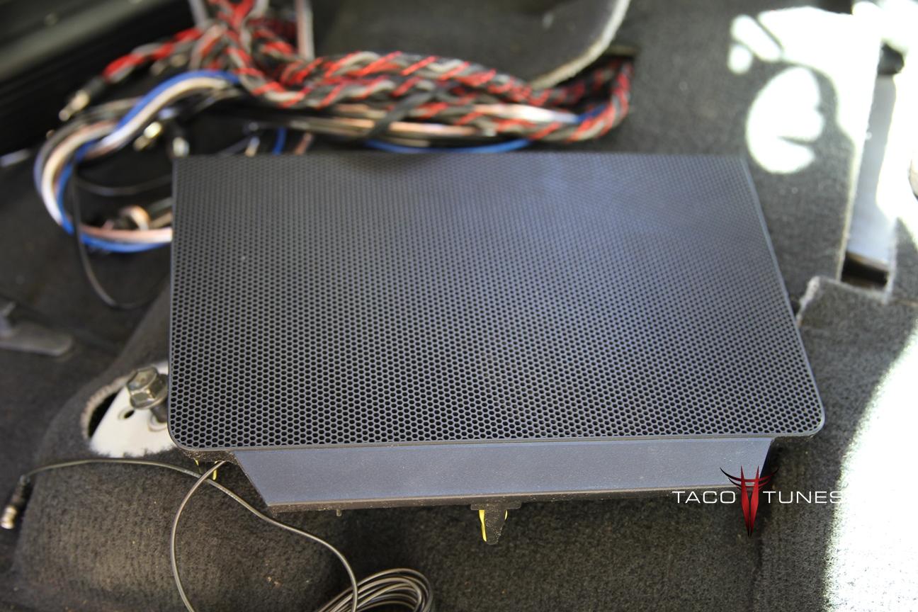
Toyota Tundra Full Size Subwoofer enclosure & Image Dynamics IDQV4 12″ 800 watt (RMS) Subwoofer
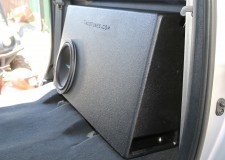
2007-2013 Toyota Tundra CrewMax Ported Subwoofer box enclosure full size subwoofer Looking for tons of bass but still want amazing clarity? Nothing will bring your music to life better than a properly tuned subwoofer enclosure matched with a powerful subwoofer. Toyota Tundra Crew Max.
The subwoofer that we include with this setup is the Image Dynamics IDQ12V4. The subwoofer can handle 800 watts (RMS) and provides deep rich bass with amazing clarity. ID is very well known for their amazing output while maintaining awesome sound quality.
NOTE: WE will not sell this subwoofer box without the subwoofer. We matched the subwoofer to the box. Properly tuning a subwoofer to an enclosure is an art / science. We refuse to allow someone to install the wrong sub in our enclosures and put our name on that enclosure.
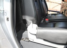
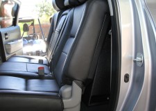
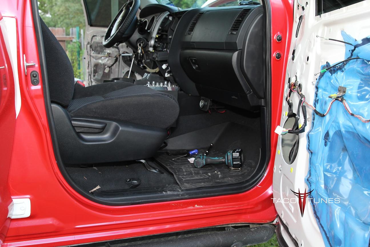
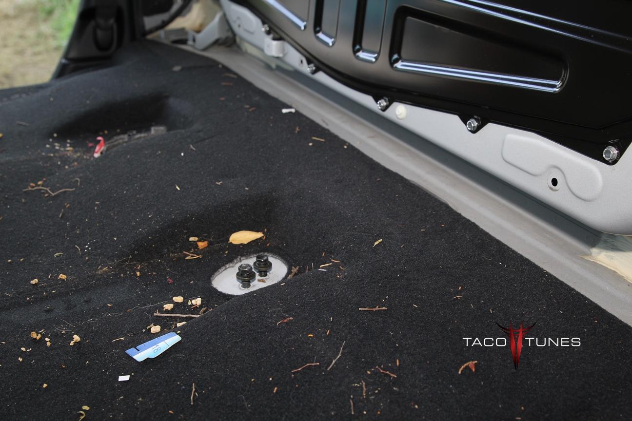
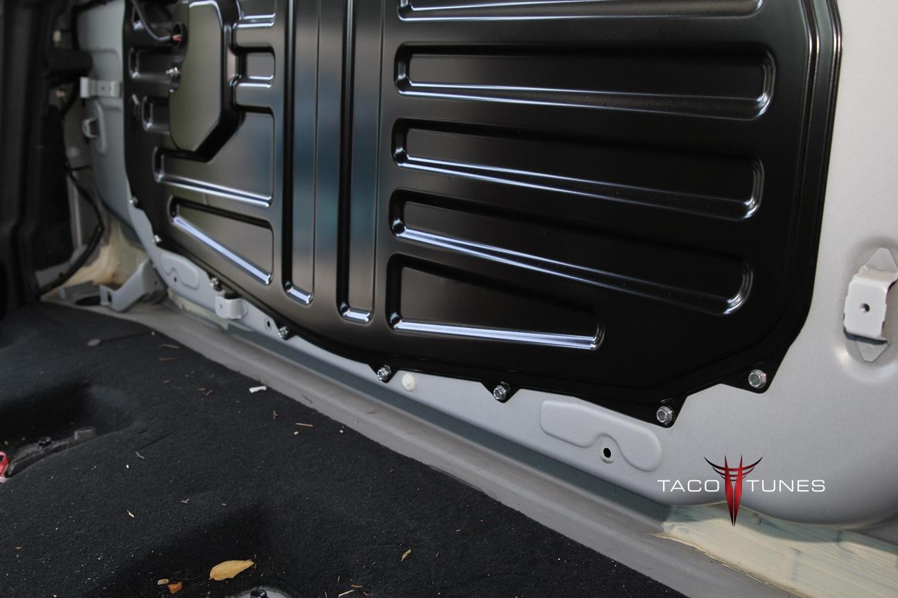
Installation Requirements:
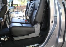
To install this subwoofer you will need to remove the rear seats to gain access. Place the sub behind the seat as shown and then use self tapping screws to affix the box to the truck. We HIGHLY suggest matting the rear wall before installing the subwoofer.
Information about Ported Boxes. A ported enclosure will generally have a better low frequency extension for a given responsive curve but generally requires a larger enclosure. Ported enclosures can’t be as small as sealed boxes . . . but a ported subwoofer box lends itself to a lower frequency response. In most cases a ported box will provide the lower end bass notes (extension) that many audio gurus are looking to obtain from their sound system. The challenge with ported boxes are MANY and can be difficult to overcome with little air space to work with. Sure it is easy to build a ported subwoofer box when you have a ton of air space! But the space behind the 2014 Tundra is nearly non-existent.
As mentioned above, the box, port design and tuning all play a crucial role in properly designing a subwoofer enclosure.
2007 – 2013
Information provided by: (Wikipedia) http://en.wikipedia.org/wiki/Thiele/Small “Thiele/Small” commonly refers to a set of electromechanical parameters that define the specified low frequency performance of a loudspeaker driver. These parameters are published in specification sheets by driver manufacturers so that designers have a guide in selecting off-the-shelf drivers for loudspeaker designs. Using these parameters, a loudspeaker designer may simulate the position, velocity and acceleration of the diaphragm, the input impedance and the sound output of a system comprising a loudspeaker and enclosure. Many of the parameters are strictly defined only at the resonant frequency, but the approach is generally applicable in the frequency range where the diaphragm motion is largely pistonic, i.e. when the entire cone moves in and out as a unit without cone breakup. Rather than purchase off-the-shelf components, loudspeaker design engineers often define desired performance and work backwards to a set of parameters and manufacture a driver with said characteristics or order it from a driver manufacturer. This process of generating parameters from a target response is known as synthesis. Thiele/Small parameters are named after A. Neville Thiele of the Australian Broadcasting Commission, and Richard H. Small of the University of Sydney, who pioneered this line of analysis for loudspeakers. History[ The 1925 paper of Chester W. Rice and Edward W. Kellogg, fueled by advances in radio and electronics, increased interest in direct radiator loudspeakers. In 1930, A. J. Thuras of Bell Labs patented (US Patent No. 1869178) his “Sound Translating Device” (essentially a vented box) which was evidence of the interest in many types of enclosure design at the time. Progress on loudspeaker enclosure design and analysis using acoustic analogous circuits by academic acousticians like Harry F. Olson continued until 1954 when Leo L. Beranek of the Massachusetts Institute of Technology published Acoustics,[1] a book summarizing and extending the electroacoustics of the era. J. F. Novak used novel simplifying assumptions in an analysis in a 1959 paper which led to a practical solution for the response of a given loudspeaker in a box, and also established their applicability by empirical measurement. In 1961, leaning heavily on Novak’s work, A. N. Thiele described a series of sealed and vented box “alignments” (i.e., enclosure designs based on electrical filter theory with well-characterized behavior, including frequency response, power handling, cone excursion, etc.) in a publication in an Australian journal.[2] This paper remained relatively unknown outside Australia until it was re-published in the Journal of the Audio Engineering Society in 1971. It is important to note that Thiele’s work neglected enclosure losses and, though a breakthrough at the time, his alignment tables now have little real-world utility. Many others continued to develop various aspects of loudspeaker enclosure design in the 1960s and early 1970s. From 1968-1972 J. E. Benson published three articles in an Australian journal that thoroughly analyzed sealed, vented and passive radiator designs, all using the same basic model. Beginning June 1972, Richard H. Small published a series of very influential articles in the Journal of the Audio Engineering Society restating and extending Thiele’s work. These articles were also originally published in Australia, where he had attended graduate school, and where his thesis supervisor was J.E. Benson. The work of Benson and Small overlapped considerably, but differed in that Benson did his work using computer programs and Small used analog simulators. Both researchers analyzed the systems including enclosure losses. Fundamental small signal mechanical parameters[edit] These are the physical parameters of a loudspeaker driver, as measured at small signal levels, used in the equivalent electrical circuit models. Some of these values are neither easy nor convenient to measure in a finished loudspeaker driver, so when designing speakers using existing drive units (which is almost always the case), the more easily measured parameters listed under Small Signal Parameters are more practical. Sd – Projected area of the driver diaphragm, in square meters. Fundamental small signal mechanical parameters[edit] These are the physical parameters of a loudspeaker driver, as measured at small signal levels, used in the equivalent electrical circuit models. Some of these values are neither easy nor convenient to measure in a finished loudspeaker driver, so when designing speakers using existing drive units (which is almost always the case), the more easily measured parameters listed under Small Signal Parameters are more practical. Sd – Projected area of the driver diaphragm, in square meters. Mms – Mass of the diaphragm/coil, including acoustic load, in kilograms.
2007 – 2013 Toyota tundra crewmax ported subwoofer box enclosure
Mass of the diaphragm/coil alone is known as Mmd Cms – Compliance of the driver’s suspension, in meters per newton (the reciprocal of its ‘stiffness’). Rms – The mechanical resistance of a driver’s suspension (i.e., ‘lossiness’) in N·s/m Le – Voice coil inductance measured in millihenries (mH) (Frequency dependent, usually measured at 1 kHz). Re – DC resistance of the voice coil, measured in ohms. Bl – The product of magnet field strength in the voice coil gap and the length of wire in the magnetic field, in tesla-metres (T·m). Qualitative descriptions[edit] Cross-section of a dynamic cone loudspeaker. Image not to scale. FsAlso called F0, resonance frequency measured in hertz (Hz). The frequency at which the combination of the energy stored in the moving mass and suspension compliance is maximum, and results in maximum cone velocity. A more compliant suspension or a larger moving mass will cause a lower resonance frequency, and vice versa. Usually it is less efficient to produce output at frequencies below Fs, and input signals significantly below Fs can cause large excursions, mechanically endangering the driver. Woofers typically have an Fs in the range of 13–60 Hz. Midranges usually have an Fs in the range of 60–500 Hz and tweeters between 500 Hz and 4 kHz. A typical factory tolerance for Fs spec is ±15%.QtsA unitless measurement, characterizing the combined electric and mechanical damping of the driver. In electronics, Q is the inverse of the damping ratio. The value of Qts is proportional to the energy stored, divided by the energy dissipated, and is defined at resonance (Fs). Most drivers have Qts values between 0.2 and 0.5, but there are valid (if unusual) reasons to have a value outside this range. QmsA unitless measurement, characterizing the mechanical damping of the driver, that is, the losses in the suspension (surround and spider.) It varies roughly between 0.5 and 10, with a typical value around 3. High Qms indicates lower mechanical losses, and low Qms indicates higher losses. The main effect of Qms is on the impedance of the driver, with high Qms drivers displaying a higher impedance peak. One predictor for low Qms is a metallic voice coil former. These act as eddy-current brakes and increase damping, reducing Qms. They must be designed with an electrical break in the cylinder (so no conducting loop). Some speaker manufacturers have placed shorted turns at the top and bottom of the voice coil to prevent it leaving the gap, but the sharp noise created by this device when the driver is overdriven is alarming and was perceived as a problem by owners. High Qms drivers are often built with nonconductive formers, made from paper, or various plastics.QesA unitless measurement, describing the electrical damping of the loudspeaker. As the coil of wire moves through the magnetic field, it generates a current which opposes the motion of the coil. This so-called “Back-EMF” (proportional to Bl * velocity) decreases the total current through the coil near the resonance frequency, reducing cone movement and increasing impedance. In most drivers, Qes is the dominant factor in the voice coil damping. Qes depends on amplifier output impedance. The formula above assumes zero output impedance. When an amplifier with nonzero output impedance is used, its output impedance should be added to Re for calculations involving Qes. BlMeasured in tesla-metres (T·m). Technically this is B×l or B×l sin(θ) (a vector cross product), but the standard geometry of a circular coil in an annular voice coil gap gives sin(θ)=1. B×l is also known as the ‘force factor’ because the force on the coil imposed by the magnet is B×l multiplied by the current through the coil. The higher the B×l value, the larger the force generated by a given current flowing through the voice coil. B×l has a very strong effect on Qes. VasMeasured in litres (L) or cubic metres, is a measure of the ‘stiffness’ of the suspension with the driver mounted in free air. It represents the volume of air that has the same stiffness as the driver’s suspension when acted on by a piston of the same area (Sd) as the cone. Larger values mean lower stiffness, and generally require larger enclosures. Vas varies with the square of the diameter. A typical factory tolerance for Vas spec is ±20–30%.MmsMeasured in grams (g) or kilograms (kg), this is the mass of the cone, coil and other moving parts of a driver, including the acoustic load imposed by the air in contact with the driver cone. Mmd is the cone/coil mass without the acoustic load, and the two should not be confused. Some simulation software calculates Mms when Mmd is entered. Mmd can be very closely controlled by the manufacturer. RmsUnits are not usually given for this parameter, but it is in mechanical ‘ohms’. Rms is a measurement of the losses, or damping, in a driver’s suspension and moving system. It is the main factor in determining Qms. Rms is influenced by suspension topology, materials, and by the voice coil former (bobbin) material. CmsMeasured in meters per newton (m/N). Describes the compliance (ie, the inverse of stiffness) of the suspension. The more compliant a suspension system is, the lower its stiffness, so the higher the Vas will be. Cms is proportional to Vas and thus has the same tolerance ranges. ReMeasured in ohms (Ω), this is the DC resistance (DCR) of the voice coil, best measured with the cone blocked, or prevented from moving or vibrating because otherwise the
2007 – 2013 Toyota tundra crewmax ported subwoofer box enclosure
pickup of ambient sounds can cause the measurement to be unreliable. Re should not be confused with the rated driver impedance, Re can be tightly controlled by the manufacturer, while rated impedance values are often approximate at best.. American EIA standard RS-299A specifies that Re (or DCR) should be at least 80% of the rated driver impedance, so an 8-ohm rated driver should have a DC resistance of at least 6.4 ohms, and a 4-ohm unit should measure 3.2 ohms minimum. This standard is voluntary, and many 8 ohm drivers have resistances of ~5.5 ohms, and proportionally lower for lower rated impedances. LeMeasured in millihenries (mH), this is the inductance of the voice coil. The coil is a lossy inductor, in part due to losses in the pole piece, so the apparent inductance changes with frequency. Large Le values limit the high frequency output of the driver and cause response changes near cutoff. Simple modeling software often neglects Le, and so does not include its consequences. Inductance varies with excursion because the voice coil moves relative to the polepiece, which acts as a sliding inductor core, increasing inductance on the inward stroke and decreasing it on the outward stroke in typical overhung coil arrangements. This inductance modulation is an important source of nonlinearity (distortion) in loudspeakers. Including a copper cap on the pole piece, or a copper shorting ring on it, can reduce the increase in impedance seen at higher frequencies in typical drivers, and also reduce the nonlinearity due to inductance modulation. Sd Measured in square meters (m²). The effective projected area of the cone or diaphragm. It is difficult to measure and depends largely on the shape and properties of the surround. Generally accepted as the cone body diameter plus one third to one half the width of the annulus (surround). Drivers with wide roll surrounds can have significantly less Sd than conventional types with the same frame diameter. XmaxSpecified in millimeters (mm). In the simplest form, subtract the height of the voice coil winding from the height of the magnetic gap, take the absolute value and divide by 2. This technique was suggested by JBL’s Mark Gander in a 1981 AES paper, as an indicator of a loudspeaker motor’s linear range. Although easily determined, it neglects magnetic and mechanical non-linearities and asymmetry, which are substantial for some drivers. Subsequently, a combined mechanical/acoustical measure was suggested, in which a driver is progressively driven to high levels at low frequencies, with Xmax determined by measuring excursion at a level where 10% THD is measured in the output. This method better represents actual driver performance, but is more
2007 – 2013 Toyota tundra crewmax ported subwoofer box enclosure
difficult and time-consuming to determine. PeSpecified in watts. Frequently two power ratings are given, an “RMS” rating and a “music” (or “peak”, or “system”) rating, usually peak is given as ~2 times the RMS rating. Loudspeakers have complex behavior, and a single number is really unsatisfactory. There are two aspects of power handling, thermal and mechanical. The thermal capacity is related to coil temperature and the point where adhesives and coil insulation melt or change shape. The mechanical limit comes into play at low frequencies, where excursions are largest, and involves mechanical failure of some component. A speaker that can handle 200 watts thermally at 200Hz, may sometimes be damaged by only a few watts at some very low frequency, like 10Hz. Power handling specifications are usually generated destructively, by long term industry standard noise signals (IEC 268, for example) that filter out low frequencies and test only the thermal capability of the driver. Actual mechanical power handling depends greatly on the enclosure in which the driver is installed. VdSpecified in litres (L). The volume displaced by the cone, equal to the cone area (Sd) multiplied by Xmax. A particular value may be achieved in any of several ways. For instance, by having a small cone with a large Xmax, or a large cone with a small Xmax. Comparing Vd values will give an indication of the maximum output of a driver at low frequencies. High Xmax, small cone diameter drivers are likely to be inefficient, since much of the voice coil winding will be outside the magnetic gap at any one time and will therefore contribute little or nothing to cone motion. Likewise, large cone diameter, small Xmax drivers are likely to be more efficient as they will not need, and so may not have, long voice coils.η0 – Reference Efficiency Specified in percent (%). Comparing drivers by their calculated reference efficiency is often more useful than using ‘sensitivity’ since manufacturer sensitivity figures are too often optimistic. SensitivityThe sound pressure, in dB, produced by a speaker in response to a specified stimulus. Usually this is specified at an input of 1 watt or 2.83 volts (2.83 volts = 1 watt into an 8 ohm load) at a distance of one meter. Mms – Mass of the diaphragm/coil, including acoustic load, in kilograms. Mass of the diaphragm/coil alone is known as Mmd Cms – Compliance of the driver’s suspension, in meters per newton (the reciprocal of its ‘stiffness’). Rms – The mechanical resistance of a driver’s suspension (i.e., ‘lossiness’) in N·s/m Le – Voice coil inductance measured in millihenries (mH) (Frequency dependent, usually measured at 1 kHz). Re – DC resistance of the voice coil, measured in ohms. Bl – The product of magnet field strength in the voice coil gap and the length of wire in the magnetic field, in tesla-metres (T·m). 2014 Toyota tundra crewmax ported subwoofer box enclosure
- Measuring Thiele Small Parameters (method 1 – the classic method)
- Measuring parameters (method 2)
- Fast Bass, Slow Bass – Myth vs. Fact
- Understanding Power Compression
- Acoustic Analogous Circuits – the method behind the formulas
2014 Toyota tundra crewmax ported subwoofer box enclosure
What size speakers fit my Toyota Toyota Tundra CrewMax
What size speakers fit my Toyota Tundra CrewMax?
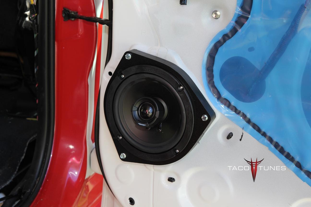
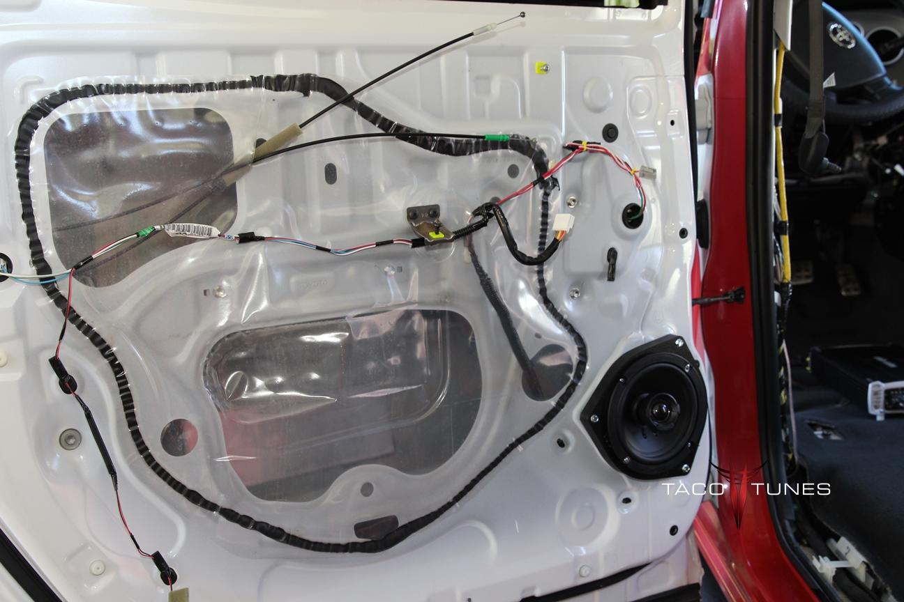
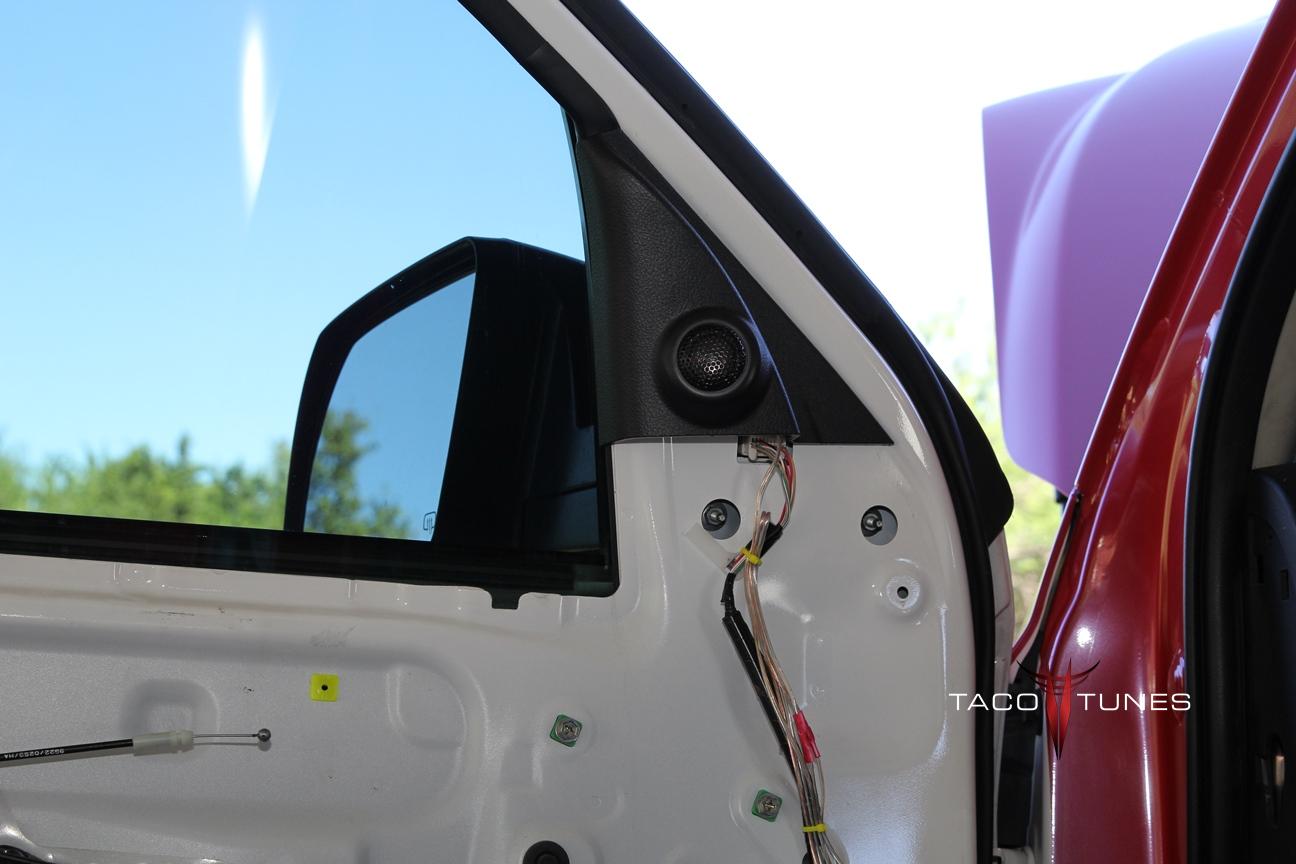
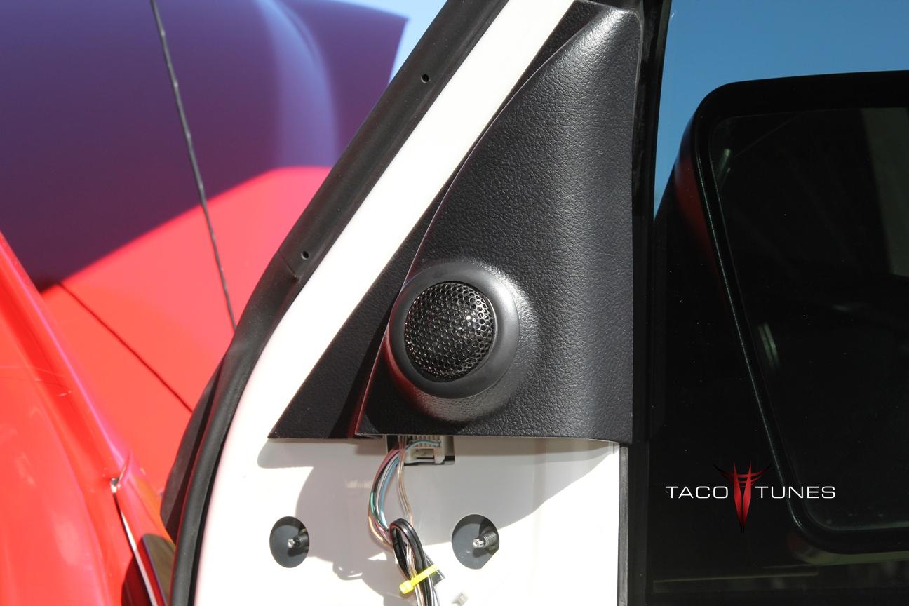
Toyota Tundra Front Doors:
[TUNDYR1]
The front doors in your Toyota Tundra CrewMax are equipped with speakers that resemble a 6×9″ aftermarket speaker. However, when you remove the stock speaker, you will need to use an adapter that allows you to install aftermarket speakers. When you use one of our speaker adapters, you can install 6×9, 6.5 or 6.75 inch coaxial and component speakers. We also offer tweeter mounting products to install aftermarket tweeters in your Toyota Tundra CrewMax. Be sure to watch our video(s) on how to select speakers that will fit into your Toyota Tundra CrewMax. If you don’t want to worry about what fits, be sure to check our our bundled speaker packages that are assured to fit your Toyota Tundra CrewMax.
Mounting Depth:
Our speaker mounting adapters for the front doors in your Toyota Tundra CrewMax are 1″ thick and they provide a top mount depth of 2.95″. This means that the speaker can not be taller than 2.95″ or it may hit the window in your Tundra. Most manufctuers will provide the top mount depth with in their speaker manual
f you are installing 6×9 speakers this will work with just about every 6×9 speaker that has a top mount depth of 2.95 inches or less. NOTE: We do offer an additional 1/4″ spacer for the Toyota Tundra CrewMax front doors that will allow a maximum top mount depth of 3.20″
Cutout / Mounting Diameter:
sizes please watch the video(s) below. It should answer most of your questions regarding speaker sizes and mounting depth.
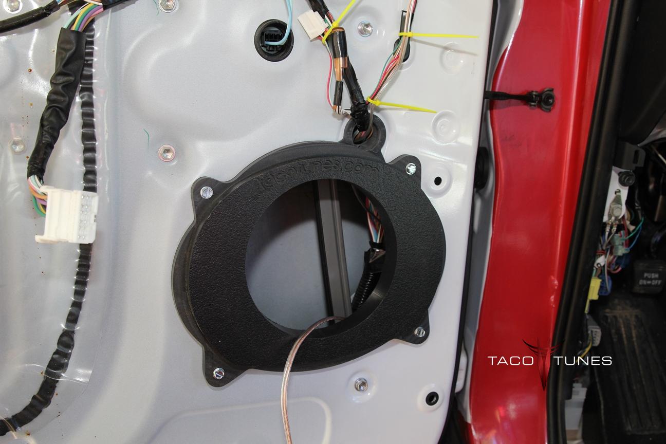
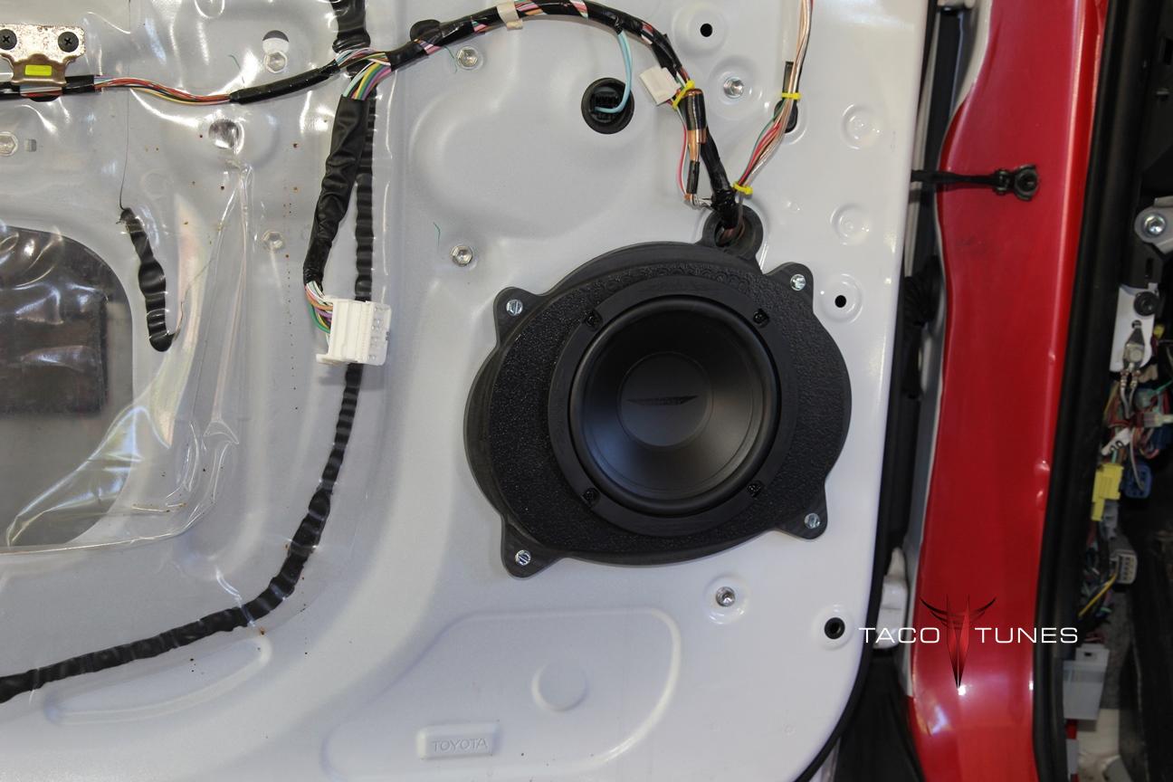
Toyota Tundra Rear Doors:
[TUNDYR1]
The rear doors in your Toyota Tundra CrewMax are equipped with speakers that resemble a 6.5″ aftermarket speaker.. However, when you remove the stock speaker, you will need to use an adapter that allows you to install aftermarket speakers. When you use one of our speaker adapters, you can install 6.5 or 6.75 inch speakers in the rear doors.Be sure to watch our video(s) on how to select speakers that will fit into your Toyota Tundra CrewMax . If you don’t want to worry about what fits, be sure to check our our bundled speaker packages that are assured to fit your Toyota Tundra CrewMax.
Our speaker mounting adapters for the rear doors in your Toyota Tundra CrewMax are 3/4″ thick and they provide a top mount depth of 3.35″. If you are planning to install 6.5 inch speakers the standard mounting diameter of 5.1 inches will accommodate approximately 90% of all 6.5 inch speakers. Higher end 6.5″ & 6.75 speakers and /or component speakers will usually have a larger mounting diameter. For more in depth explanation of speaker sizes, please watch the video(s) below. It should answer most of your questions regarding speaker sizes and mounting depth.
CLICK HERE TO SHOP FOR TOYOTA AUDIO PRODUCTS


| Alphasonik | Coustic | Jensen | Neon Lights | RCA |
| Alpine | Crimestopper | JL Audio | Nitro | RE Audio |
| Alumapro | Crossfire | JVC | Optima | Rockford Fosgate |
| American International | Custom Boxes | Kenwood | Orion | Sansui |
| ARC Audio | DEI | Kenwood Excelon | OZ Audio | Scosche |
| Audiobahn | DHD | Kicker | PAC | Scytek Alarms |
| AudioControl | Diamond Audio | Kinetik | Package | Solobaric Boxes |
| Audiosource | DLS | Kole Audio | Panasonic | Sony |
| Audiovox | Dual | Lanzar | Performance Teknique | Soundstream |
| Audison | DUB Mag Audio | Legacy | Phoenix Digital | Stinger |
| Avionixx | Dynamat | Lightning Audio | Phoenix Gold | Tidus |
| Bazooka | Dynaudio | MA Audio | Pioneer | Tsunami |
| BMA | Earthquake | MB Quart | Polk Audio | U.S. Acoustics |
| Boss | Eclipse | McIntosh | Power Acoustik | US Amps |
| Boston Acoustics | Farenheit | Memphis | Power Supplies | Valor |
| Brax | Focal | Mmats | Powerbass | Viper |
| Cadence | Helix | Monster Cable | Precision Power | Visonik |
| CDT Audio | Hifonics | Morel | Prestige | Volfenhag |
| Cerwin Vega | Image Dynamics | MTX | Profile | XO Vision |
| Clarion | Infinity | MTX Thunderforms | Pyle | Xpress |
| Cobra | JBL | Nakamichi | Rainbow | Zapco |
What size speakers fit my Toyota Tundra CrewMax
What size speakers fit my Toyota Tacoma Double Cab
What size speakers fit my Toyota Tacoma Double Cab?
Toyota Tacoma Front Doors:
[TACOYRDC_2]
The front doors in your Toyota Tacoma Double Cab are equipped with speakers that resemble a 6×9″ aftermarket speaker. However, when you remove the stock speaker, you will need to use an adapter that allows you to install aftermarket speakers. When you use one of our speaker adapters, you can install 6×9, 6.5 or 6.75 inch coaxial and component speakers. We also offer tweeter mounting products to install aftermarket tweeters in your Toyota Tacoma Double Cab. Be sure to watch our video(s) on how to select speakers that will fit into your Tacoma Double Cab. If you don’t want to worry about what fits, be sure to check our our bundled speaker packages that are assured to fit your Toyota Tacoma Double Cab.
Our speaker mounting adapters for the front doors in your Toyota Tacoma Double Cab are 1″ thick and they provide a top mount depth of 3.25″. If you are installing 6×9 speakers this will work with just about every 6×9 speaker that has a top mount depth of 3.25 inches or less. If you are planning to install 6.5 inch coaxial speakers the standard mounting diameter of 5.1 inches will accommodate approximately 90% of all 6.5 inch speakers. Higher end 6.5″ & 6.75 speakers and /or component speakers will usually have a larger mounting diameter. For more in depth explanation of speaker sizes please watch the video(s) below. It should answer most of your questions regarding speaker sizes and mounting depth.
Toyota Tacoma Rear Doors:
[TACOYRDC_2]
The rear doors in your Toyota Tacoma Double Cab are equipped with speakers that resemble a 6.5″ aftermarket speaker.. However, when you remove the stock speaker, you will need to use an adapter that allows you to install aftermarket speakers. When you use one of our speaker adapters, you can install 6.5 or 6.75 inch speakers in the rear doors.Be sure to watch our video(s) on how to select speakers that will fit into your Toyota Tacoma Double Cab . If you don’t want to worry about what fits, be sure to check our our bundled speaker packages that are assured to fit your Toyota Tacoma Double Cab.
Our speaker mounting adapters for the rear doors in your Toyota Tacoma Double Cab are 3/4″ thick and they provide a top mount depth of 3.35″. If you are planning to install 6.5 inch speakers the standard mounting diameter of 5.1 inches will accommodate approximately 90% of all 6.5 inch speakers. Higher end 6.5″ & 6.75 speakers and /or component speakers will usually have a larger mounting diameter. For more in depth explanation of speaker sizes, please watch the video(s) below. It should answer most of your questions regarding speaker sizes and mounting depth.
CLICK HERE TO SHOP FOR TOYOTA AUDIO PRODUCTS
Below is a video instructional video that will show you how to remove the door panel and installs speakers in a Toyota Tacoma Toyota Tacoma Double Cab Access cab & Xrunner.
| Alphasonik | Coustic | Jensen | Neon Lights | RCA |
| Alpine | Crimestopper | JL Audio | Nitro | RE Audio |
| Alumapro | Crossfire | JVC | Optima | Rockford Fosgate |
| American International | Custom Boxes | Kenwood | Orion | Sansui |
| ARC Audio | DEI | Kenwood Excelon | OZ Audio | Scosche |
| Audiobahn | DHD | Kicker | PAC | Scytek Alarms |
| AudioControl | Diamond Audio | Kinetik | Package | Solobaric Boxes |
| Audiosource | DLS | Kole Audio | Panasonic | Sony |
| Audiovox | Dual | Lanzar | Performance Teknique | Soundstream |
| Audison | DUB Mag Audio | Legacy | Phoenix Digital | Stinger |
| Avionixx | Dynamat | Lightning Audio | Phoenix Gold | Tidus |
| Bazooka | Dynaudio | MA Audio | Pioneer | Tsunami |
| BMA | Earthquake | MB Quart | Polk Audio | U.S. Acoustics |
| Boss | Eclipse | McIntosh | Power Acoustik | US Amps |
| Boston Acoustics | Farenheit | Memphis | Power Supplies | Valor |
| Brax | Focal | Mmats | Powerbass | Viper |
| Cadence | Helix | Monster Cable | Precision Power | Visonik |
| CDT Audio | Hifonics | Morel | Prestige | Volfenhag |
| Cerwin Vega | Image Dynamics | MTX | Profile | XO Vision |
| Clarion | Infinity | MTX Thunderforms | Pyle | Xpress |
| Cobra | JBL | Nakamichi | Rainbow | Zapco |
What size speakers fit my Toyota Tacoma Double Cab